Search results
Query: low power amp
Links: 61 | Categories: 0
-
 KISS703 is a 703 Hz narrowband digital mode for amateur radio, designed for simple, low-power operation without computers. A 500 Hz pilot tone ensures frequency alignment, replaced by unique tones for 37 symbols (letters, numbers, space). Built from common discrete components, it draws about 40 mA at 12 V, ideal for SOTA/IOTA use. The receiver uses amplification, wave shaping, and a pulse-counting frequency meter for manual decoding via a calibrated meter. Transmitter and receiver calibration involves marking meter positions for each tone, enabling fully self-contained messaging with minimal hardware in portable or fixed operations.
 -
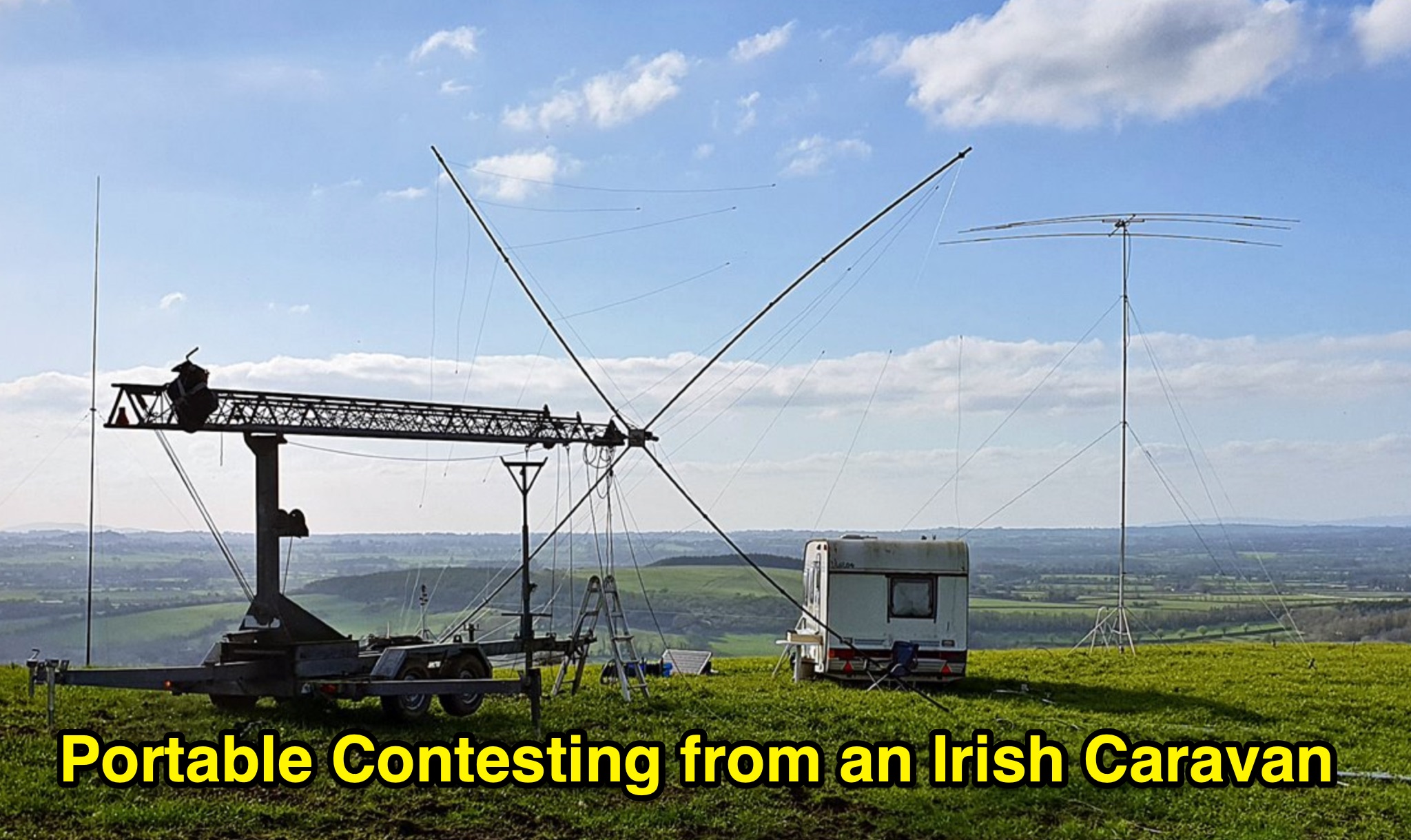 This blog chronicles over a decade of portable HF contesting from rural Ireland (2008–2019) by Olivier, operating under callsigns EI/ON4EI, EI8GQB, EI1A, and EI7T. Using only green energy from a caravan, he achieved top-tier results in major international contests—including 1st World in the 2018 IARU HF Championship (SSB LP) and multiple 1st-place finishes in CQ WW and CQ WPX SSB Europe. Operating in the demanding Single Operator All Band Low Power and SO2R categories, he deployed up to five antennas across five bands, often in remote or emergency-style conditions. The narrative blends technical detail, fieldcraft, and personal reflection, documenting triumphs, setbacks (including carbon monoxide poisoning), and the logistical challenges of sustainable portable operation—culminating in his decision to transition to team-based contesting and future DXpeditions.
 -
 The Olivia digital mode, a **Multi-Frequency Shift Keying (MFSK)** radioteletype protocol, is specifically engineered for robust communication under difficult propagation conditions on shortwave radio bands from 3 MHz to 30 MHz. Developed by Pawel Jalocha in 2003, Olivia signals can be decoded even when the noise amplitude exceeds the digital signal by over ten times, making it highly effective for transmitting ASCII characters across noisy channels with significant fading and propagation phasing. Early on-the-air tests by Fred OH/DK4ZC and Les VK2DSG on the Europe-Australia 20-meter path demonstrated intercontinental contacts with as little as one-watt RF power under favorable conditions. Common Olivia modes are designated as X/Y, where X represents the number of tones and Y is the bandwidth in Hertz, with examples including 8/250, 16/500, and 32/1000. The resource clarifies that Olivia, unlike some other digital modes, produces a constant envelope, allowing RF power amplifiers to achieve greater conversion efficiencies and making it less prone to non-linearity. Operators are advised that **Automatic Level Control (ALC)** can be set higher than no meter movement for MFSK modulation, as long as it's not driven past its high limit, contrary to common misinformation about other digital modes. The Olivia community encourages voluntary channelization on suggested calling frequencies, such as 14.0725 MHz for 8/250, to facilitate initial contacts, especially for signals below the noise floor. The Olivia Digital DXers Club provides links to Groups.io, Facebook, and Discord for community engagement and offers details on QSO parties.
 -
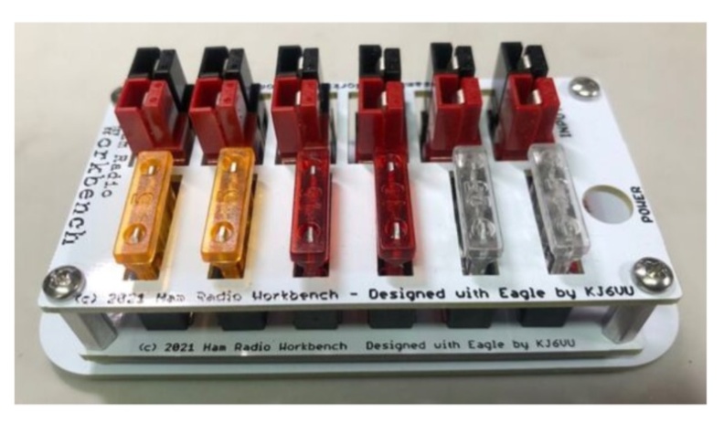 The **5-Port 12 Volt DC Power Strip Kit (Rev 4)** offers a practical solution for managing shack power distribution, providing one input and five fused outputs. All connections utilize the ubiquitous Anderson PowerPole connectors, a standard for many amateur radio operators, ensuring a clean, organized, and safe way to power multiple 12 VDC transceivers and accessories from a single source. This design mitigates the common issue of tangled wires and overloaded connections in a typical ham shack. Rated for a maximum current of 20 Amps at 12 VDC, the strip incorporates an integrated LED to indicate when external power is applied. Each output is individually fused, a critical safety feature that protects connected equipment from overcurrent conditions without affecting other devices on the strip. This level of protection is essential for preserving sensitive radio gear during operation. Assembly requires basic soldering skills and hand tools, with a high-power soldering iron and wide chisel tip specifically recommended for best results. The kit's compact dimensions of 4.13" x 1.78" allow for flexible mounting via screw holes, making it suitable for various shack configurations and portable operations.
 -
 Details the construction and performance of a phase-controlled receiving array, specifically a **MicroSWA** variant, optimized for QRP low band fox hunting on 40M and 80M. The resource documents the author's iterative design process, addressing significant regional noise challenges encountered during 0100-0230 UTC fox hunt periods. Initial experiments involved a director wire on a 40M vertical, yielding limited improvement, prompting a shift towards advanced null-steering techniques. The project leverages concepts from Victor Misek’s "The Beverage Antenna Handbook" and Dallas Lankford’s extensive work on phased receiving antennas for urban lots. A key modification involved integrating a new passive phase control box and a push-pull **Norton common base preamp** using 2N5109 transistors, designed for high third-order intercept performance to maintain weak signal integrity amidst strong adjacent signals. The system incorporates Faraday-shielded transformers with RG174 primaries on -75 ferrite cores, housed in ABS plastic pipe. Performance tests confirmed the MicroSWA's ability to produce deep, steerable nulls, achieving approximately 30 dB noise reduction on 160M, 80M, and 40M. This enabled detection of QRP signals undetectable on conventional transmit antennas. The final unit includes front panel controls, a 10-11 dB preamp, and a robust power conditioner, demonstrating effective noise mitigation for challenging low band QRP operations.
 -
 An Arduino-based interface provides a remote tuner call command for Icom **IC7700** and **IC7800** transceivers, addressing the lack of a built-in function for external tuners such as the MFJ 998RT. This setup initiates a low-power transmit signal, typically 15 watts, allowing the remote autotuner to perform its matching sequence. The article details the required CI-V line communication and modifications to existing Arduino code, specifically referencing contributions from Jean-Jacques ON7EQ for improved Icom interrogation routines. The system involves a sequence of steps: storing the transceiver's current mode and power, disabling the internal autotuner, activating a control relay to interrupt the amplifier line, switching to RTTY mode at low power, and initiating transmit. The transmit duration is manually controlled by the operator, observing the SWR meter until a low SWR is achieved, then a second button press stops the transmission. A built-in 4-second transmit limit provides a safety measure. After tuning, the routine restores the original mode and power settings, re-enables the internal autotuner, and performs a brief 2-second RTTY transmission for internal tuner adjustment. The circuit diagram includes a Panasonic form 2 relay for amp control and emphasizes critical delays in the Arduino code for stable operation at 9600 baud CI-V communication. Compatibility with logging software like DXLab, N1MM, and N3FJP is noted, with specific interrogation time settings required to avoid conflicts.
 -
 The Gemini Amplifier Remote Control software operates on Windows 7 and above, facilitating remote management of the Gemini HF-1K and DX-1200 amplifiers. Users connect via Ethernet, configuring the amplifier's IP address through the front panel. The software allows seamless band and antenna selection, saving settings for each band without requiring transmission. Integration with _OmniRig_ from Afreet Software, Inc. enables automatic band adjustments based on the radio's frequency changes. Users can configure serial or virtual serial connections, with tracking options accessible through the ribbon bar. The software supports speech functionality, enhancing accessibility for operators. Firmware updates, such as version 2.5Ee, introduce features like background datalogging and power output control, uploaded via FTP. Version 1.2.0 allows users to offload internal parameter data for support purposes. The firmware upload process requires the amplifier's IP address and port 21, taking approximately 90 seconds. Users are encouraged to upgrade to the latest firmware for improved performance and remote diagnostics.
 -
 This resource details **cooling modifications** for Ameritron AL82, AL1200, and AL1500 HF amplifiers, specifically addressing heat issues encountered during high-duty-cycle digital mode operation. The author, WD4NGB, observed excessive heat in the tank area and band switch on an AL82, attributing it to insufficient exhaust over the 3-500 tubes and a complete lack of exhaust over the tank area. The modifications aim to prevent common failures such as damaged band switches and deformed insulating materials by increasing airflow and exhaust area. The page describes adding five holes to the chassis for enhanced cooling to the band switch and tank area, alongside enlarging the exhaust area over the inner 3-500 tube and the tank area on the amplifier cover, utilizing expanded metal for safety and RF shielding. The original cover featured 26.25 square inches of exhaust; the modified version significantly increases this to 48.5 square inches over the tubes and introduces an additional 15 square inches over the band switch. These changes are intended to resolve heating problems encountered during heavy, 100% duty cycle use in modes like RTTY or long SSB contests, which typically generate substantial heat. The article also discusses upgrading to a higher output fan, such as the G2E085-AA05-21, and modifying tube sockets for improved airflow and reduced back pressure, citing Tom Rauch (W8JI) of CTR Engineering as a source for parts.
 -
 The W6PQL 23cm Beacon Project describes a **1296 MHz** beacon designed for microwave propagation studies and equipment testing, capable of 30 watts output. It utilizes a PIC 16F628A microcontroller to generate CW and FSK keying for a crystal oscillator, followed by a series of frequency doublers and triplers to reach the target frequency. The final power amplification stage employs a Mitsubishi M57762 module, providing a robust 10-watt RF output. The design emphasizes stability and reliability for continuous operation, with the microcontroller code, written in assembly, provided for customization of the beacon's callsign and message. Originally located in CM97am and aimed at 140 true, the beacon used four 4-foot Yagis stacked vertically for a total ERP of 3kW. The article includes schematics, parts lists, and construction notes to guide builders, along with antenna pattern measurements. Although the beacon itself is no longer in service as of August 2010, the detailed documentation remains a valuable reference for amateur radio operators interested in building similar **microwave** projects or understanding beacon operation.
 -
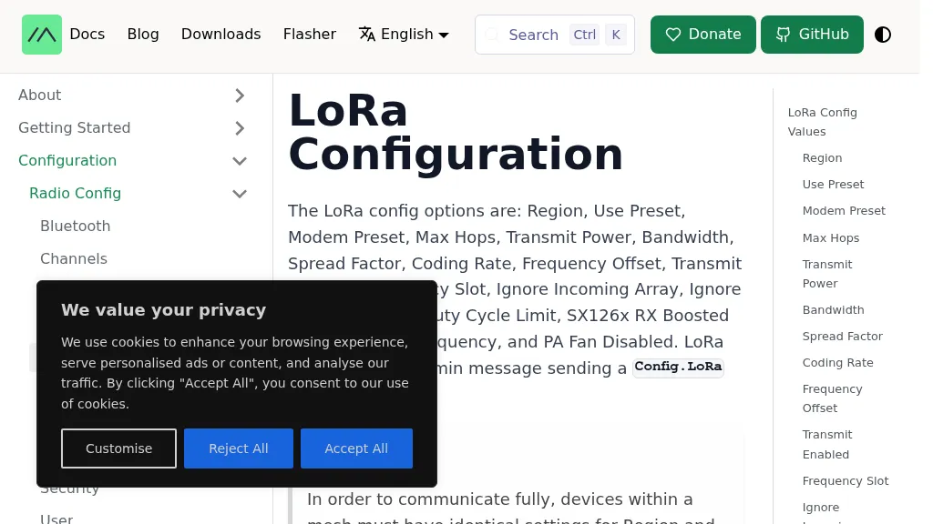 The Meshtastic documentation outlines critical LoRa configuration parameters for node operation, emphasizing regulatory compliance. It details settings such as Region, Modem Preset, Max Hops, Transmit Power, Bandwidth, Spread Factor, Coding Rate, and Frequency Offset. A comprehensive table provides region codes, frequency ranges (e.g., US **902.0 - 928.0 MHz**), duty cycles, and power limits (e.g., EU_433 **12 dBm**) for numerous countries, including the US, EU, China, and Japan, alongside a 2.4 GHz band option. It explicitly states that devices within a mesh must share identical _Region_ and _Modem Preset_ settings for full communication. Modem Presets, like _LONG_FAST_ (the default), optimize for either speed or range, directly impacting network congestion and message delivery delay. For instance, SHORT_TURBO offers the fastest speed and shortest range, while VERY_LONG_SLOW provides the longest range but is less reliable for mesh formation. The document also highlights specific duty cycle limitations, such as the 10% hourly limit for EU_433 and EU_868 regions, and provides command-line interface (CLI) examples for configuring these parameters.
 -
 This online construction guide details the assembly of a signal generator specifically for the **13cm band** (2.4 GHz). The curriculum focuses on the integration of a Voltage Controlled Oscillator (VCO), specifically the ROS-2400, to produce a stable RF signal. The resource outlines the necessary components for frequency generation and output, including the use of a Mini-Circuits MMIC amplifier for signal conditioning. The construction protocol involves configuring the ROS-2400 VCO to operate within the 2.3 GHz to 2.45 GHz range, ensuring frequency coverage for amateur radio _microwave experimentation_. The guide specifies the output power level, approximately 70mW, directly from the MMIC stage, indicating its application as a low-power instrumentation source rather than a transmit-capable device. This project provides a practical example of constructing a dedicated test instrument for microwave frequency measurements and system alignment on the **13cm band**. DXZone Focus: Construction Guide | 13cm Signal Generator | VCO Integration | Microwave Experimentation