Search results
Query: multi-band hf
Links: 53 | Categories: 2
-
 John Lemay’s (G4ZTR) review of the Yaesu FT-847 offers a practical look at this all-mode transceiver, spanning 160m to 70cm, including 4m. While it falls short in dynamic range and sensitivity, its "shack-in-a-box" design shines for VHF DXing and multi-band use. Lemay shares hands-on tweaks, like calibrating 70cm with beacons and integrating footswitches for SSB and CW. The TX Inhibit feature simplifies sequencing with external gear. Despite minor flaws, the FT-847’s versatility and mod-friendly nature make it a solid pick for amateur radio enthusiasts craving flexibility.
 -
 The Zeppelin antenna, a J-type design, is presented as a two-band HF dipole, offering independent operation on harmonically related frequencies. This resource details its electrical configuration, comprising a half-wave radiator end-fed by a quarter-wave matching section, and explores its historical evolution from early Zeppelin airship applications to modern amateur radio use. The article specifically examines how a Zepp antenna tuned to 28.4 MHz (10 meters) exhibits a harmonic relationship with 15.4 MHz (20 meters), noting a frequency ratio of approximately 1.84:1, which deviates from a perfect 2:1 due to factors like elevation, wire separation, velocity factor, and end-effect. Antenna modeling results, including SWR sweeps at 28.4 MHz (1.1 SWR) and 15.4 MHz (1.6 SWR), are provided through Graph 1 and Graph 2, illustrating the antenna's performance across these bands. Current distribution patterns for both the 28.4 MHz (second harmonic) and 15.4 MHz (first harmonic) operations are visually represented in Figure 2 and Figure 3, respectively. The author also includes a 4NEC2 model's "Symbol Conversion file" definitions and calculated #14 wire dimensions for achieving resonance at 28.4 MHz, with the antenna positioned at a height of 33 feet. The discussion further highlights the antenna's versatility, suggesting its potential as a single-band, center-fed, 15.4 MHz half-wave folded end dipole when fed at a specific low current point. This analysis provides practical insights into constructing and optimizing a multi-band Zepp antenna for HF operations, emphasizing its unique harmonic characteristics and physical compactness.
 -
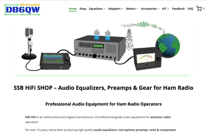 Optimizing on-air audio for SSB, DXing, and contesting operations is addressed through a range of specialized audio processing equipment. The offerings include multi-band equalizers, specifically 5-band, 8-band, 10-band, and 12-band units, some integrated with features such as compressors, echo effects, noise gates, and phase rotation capabilities. These devices are engineered to interface with common amateur radio transceivers, with explicit compatibility noted for models like the Yaesu FT-DX10, FT-DX101D, FT-1000MP, FT-DX5000, Collins HF-380, and Flex 6300, alongside analog S/P meters for Icom rigs. The product line focuses on enhancing microphone audio characteristics, supporting XLR dynamic microphones for improved signal clarity and presence. The manufacturer, DB6QW Electronics, emphasizes direct support and a 100% manufacturer's warranty, reflecting confidence in product quality and operational reliability. This resource details specific audio processing tools designed to refine the transmitted audio signal, providing operators with granular control over their voice characteristics for competitive and casual amateur radio communications.