Search results
Query: reflector
Links: 78 | Categories: 0
-

-
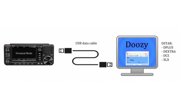 With Doozy for Windows you can make QSO’s via your Windows PC on DSTAR ( DPLUS, DEXTRA, DCS and XLX ). There is no need for a hotspot. Just connect your ICOM IC-705 to your Windows PC with an USB datacable and connect it to your favorite DSTAR reflector/repeater.
 -
 The Horn reflector antenna at Bell Telephone Laboratories
 -
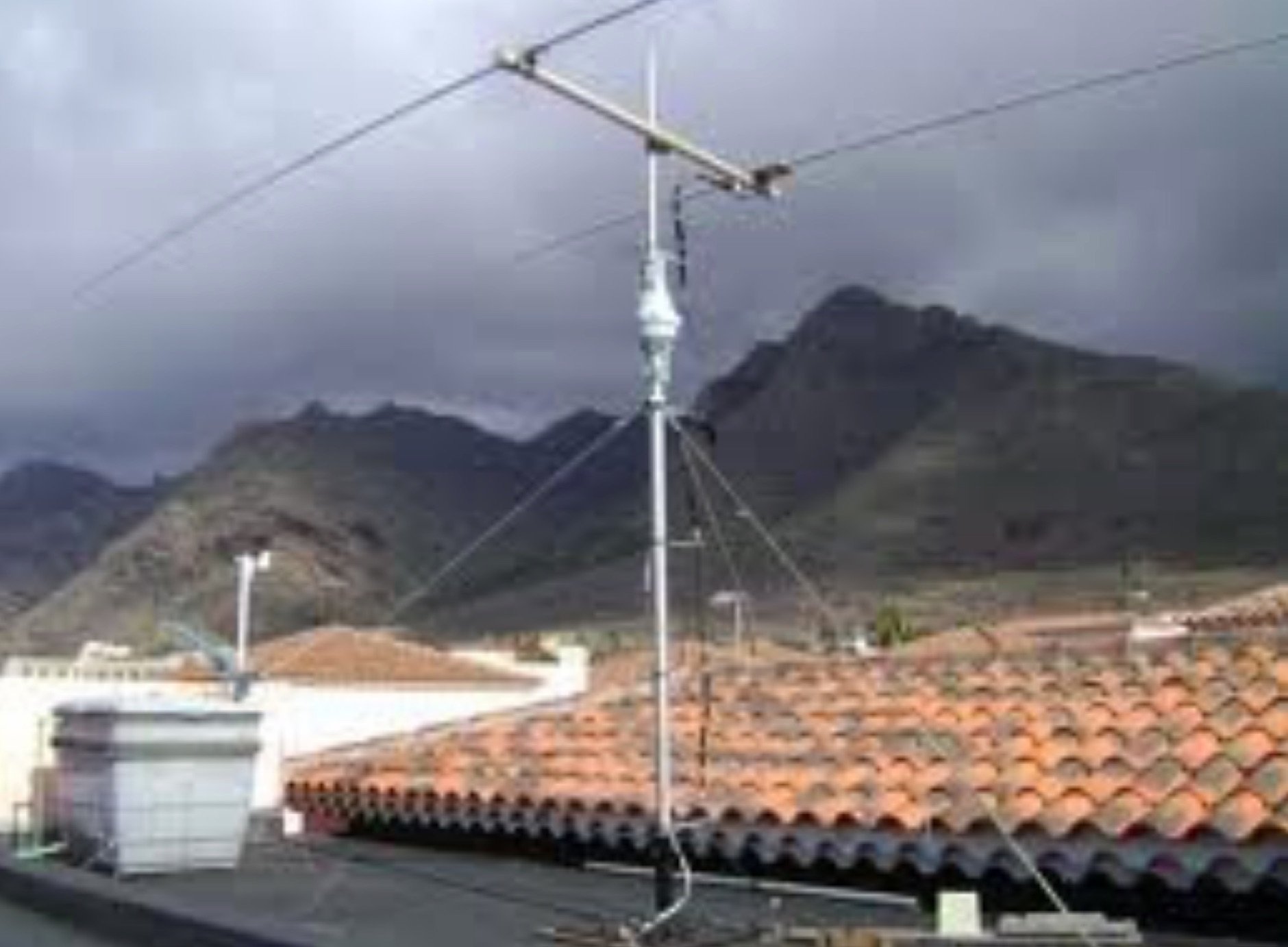 The Maria Maluca HF multiband antenna as designed in 1957 by PY2BBP is a directive antenna for 15 meter and a passive element that works as director and reflector in different bands
 -
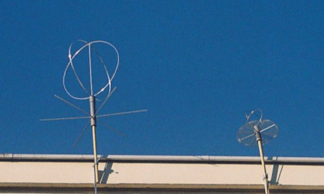 This antenna was conceived mainly for high-speed digital transmission via satellite. The antenna is made of two full waves loops , mounted at right angles to each other. Then coupled together, 90 degrees out of phase over a horizontal circular reflector. With this configuration the antenna is omni directional and circularly polarized.
 -
 Operating as a hub for its members, the Club Radioamateur Sorel-Tracy VE2CBS Inc. website provides essential information regarding club activities, membership management, and technical resources. It features articles on topics such as **D-STAR** digital voice mode training, offering a multi-capsule course for members to understand, configure, and effectively use D-STAR with ICOM equipment, including callsign routing and reflector connections. The site also details access to member cards, renewal processes, and upcoming events like the annual HAMFEST, which serves as a significant gathering for local radio amateurs. Beyond club-specific news, the site curates information on useful amateur radio tools and technologies, exemplified by articles on **HamClock** for propagation and satellite tracking, and a quick guide to Meshtastic for LoRa-based mesh networking. These resources aim to support members in exploring modern digital modes and enhancing their station operations, reflecting the club's commitment to fostering technical knowledge and community engagement within the Sorel-Tracy amateur radio scene.
 -
 The Kentucky Contest Group (KCG) website, maintained by N4GN, serves as a hub for amateur radio operators interested in **radiosport** contesting within Kentucky and southern Indiana. It details the group's dedication to promoting contesting, offers links to KCG officers, membership rosters, and upcoming meetings, and provides access to an active KCG e-mail reflector and Facebook Group for member communication. The site also features a comprehensive list of N4GN's recommended ham radio web picks, covering various categories like contesting resources, DXing, VHF/UHF/Microwave, and propagation information. The KCG's map center coordinates were updated on May 16, 2015, shifting approximately 16.5 miles SSW to 37° 21' N, 85° 39' W. Despite acknowledging current inactivity and an outdated web presence, the group remains operational, exploring options for reorganization, including a potential merger with the Tennessee Contest Group (TCG), which was ultimately rejected. The site emphasizes that membership applications are considered from anyone with a genuine interest in contesting.
 -
 The video delves into the fascinating science behind antennas, which are crucial for receiving and transmitting electromagnetic waves. It explains how antennas convert electric signals into electromagnetic waves for transmission, and how they operate through the oscillation of positive and negative charges in dipole arrangements. Practical antenna implementations, such as dipole antennas for TV reception and Yagi-Uda antennas with reflectors and directors, are also discussed alongside modern dish TV antennas with parabolic reflectors for signal processing. It's a comprehensive overview of how antennas work and their significance in communication technology.
 -
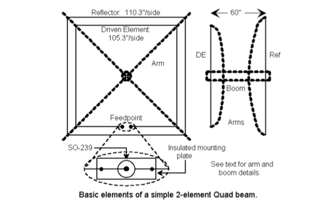 Quads beams consist of 2 1 wavelength (approximately) loops, ordinarily arranged so that one is the driven element and the other is the reflector. In this project author explains how to build a two element Quad Antenna for the 28 MHz.
 -
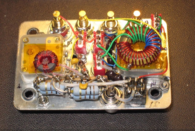 This is a detailed, technical piece, intended mostly for makers and more creative activators, who enjoy building and using their own tools on the summits. A multiband portable antenna tuner supporting 10W, small and light, suitable for SOTA operations
 -
 Clarifies the intricate process of calibrating the _Elecraft K2_ dial, addressing common user challenges and lively discussions on the Elecraft reflector. Wilhelm, W3FPR, dissects the K2's PLL synthesizer design, chosen for its low phase noise, kit-friendly duplication, and cost-effective components. The resource emphasizes the critical role of the 4000.000 kHz reference oscillator's accuracy during CAL PLL, CAL FIL, and CAL FCTR functions, noting its dependence on temperature and crystal stability for optimal performance. Explaining the K2's frequency display, the document reveals it relies on microprocessor-driven look-up tables generated by CAL PLL for VFO values and CAL FIL for BFO values. In SSB and RTTY, these combine, while CW and CWr modes also factor in the sidetone pitch. The author details inherent limitations, such as the 10 Hz increment resolution of the dial and varying PLL step sizes—from 3 Hz on 160 meters to 10 Hz on 10 meters. BFO increments range from 20 to 35 Hz, collectively limiting practical dial accuracy to within **20 Hz** with diligent effort, or **30 Hz** for a slightly less demanding task. The guide outlines a four-step calibration procedure: setting the reference oscillator, running CAL PLL, running CAL FIL, and setting all BFOs. It highlights the _N6KR Method_ as a particularly easy and accurate approach, requiring only the K2 and a known frequency source like WWV for zero-beating, eliminating the need for external test equipment.
 -
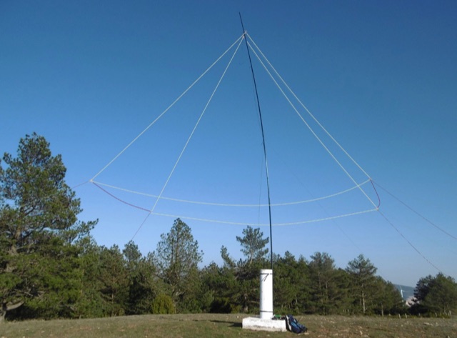 A light portable 2 element Delta beam antenna for 14 MHz. It is basically a two element delta loop wire antenna made for portable usage providing good directivity and a 4.2 dBd gain
 -
 Constructing a directional antenna for VHF operations, particularly for 2-meter band contests or local communication, often involves balancing performance with ease of build. The Moxon rectangle, a compact two-element beam, offers a good front-to-back ratio and gain in a smaller footprint compared to a Yagi, making it suitable for portable or temporary setups where space is limited. This design typically uses a driven element and a single reflector, bent into a rectangular shape to achieve its unique radiation pattern. The article details the construction of a 2-meter Moxon antenna, specifically for 144 MHz, utilizing readily available materials like PVC pipe for the frame and copper wire for the elements. It outlines the dimensions for the driven element at 970mm and the reflector at 910mm, with a spacing of 140mm between them, and a 50mm gap at the element ends. The feedpoint is a direct 50-ohm connection, simplifying matching requirements. The project includes a parts list, a basic diagram illustrating the element layout and dimensions, and photographs of the completed antenna. The author notes the antenna's performance during a QRP contest, achieving contacts up to 100km with 5 watts, demonstrating its effectiveness for low-power VHF work.
 -
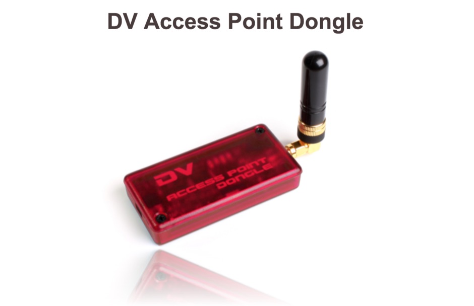 The DV Access Point Dongle connects to your PC or Intel based Mac via a USB port and provides a 2 meter Access Point for use with a D-STAR radio. Using an Internet connection, a user may connect to and communicate with D-STAR gateways and reflectors around the world
 -
 The DK7ZB-Dualband-Moxon-Beam provides a compact, high-performance antenna solution for 28 MHz and 50 MHz operations, utilizing a single 50-ohm feedpoint. This design functions as a mini-beam on 10 meters, achieving a gain of **4.0 dBd** with a front-to-back ratio of _30 dB_, while operating as a 2-element Yagi on 6 meters, yielding a gain of **4.3 dBd** and an 11 dB F/B ratio. The antenna's dimensions are approximately two-thirds that of a full-size 10-meter beam, making it suitable for smaller spaces. Construction details include a parts list specifying aluminum tubes of various diameters and lengths for the reflector and radiator elements. Builders like Aleks (S54S) and Marcio (PY2OK) have successfully replicated the design, with Aleks noting the utility of bending corners during assembly. Fine-tuning is accomplished by adjusting the length of specific elements that slide into larger tubes. The feeding system incorporates a balun, with options for either 300 watts using RG188 on an FT140-43 core or 1 kilowatt using _Aircell-5_ on an FT240-43 core, ensuring versatility for different power levels.
 -
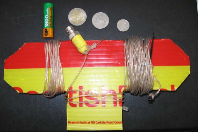 The reason for making this antenna was the desire for a vertical (hence DX-ish) antenna that would cover at least 20m that would fit on my 5m fishing pole. This antenna can work on 20m 17m 15m bands and it is suitable for SOTA operations
 -
 Documents the design and construction of a **four-band Moxon beam** antenna, covering 20, 15, 10, and 6 meters. Author W7JMP shares his journey from initial research and computer modeling using 4NEC2 to the final on-air testing and optimization. The project aimed for gain over a dipole on 20 meters, with a budget under $500, including the antenna rotor. The design incorporates fiberglass spreaders and a single feedpoint, avoiding complex relay switching. The article details the selection of materials, assembly techniques, and the critical tuning process. W7JMP describes fabricating the hub, mounting spreaders, and attaching elements made from stripped THTN wire. A notable innovation is the use of a half-wave tuning stub with a loading coil for in-situ adjustment of the 20-meter reflector, optimized via remote S-meter readings using a webcam and smartphone. This method allowed for fine-tuning the **front-to-back ratio** without lowering the antenna. Initial testing revealed a dipole-like pattern, which was significantly improved after tuning, resulting in reported 2 to 4 S-unit front-to-back ratios and enhanced signal strength for DX contacts on multiple bands, including sporadic E on 10 and 6 meters.
 -
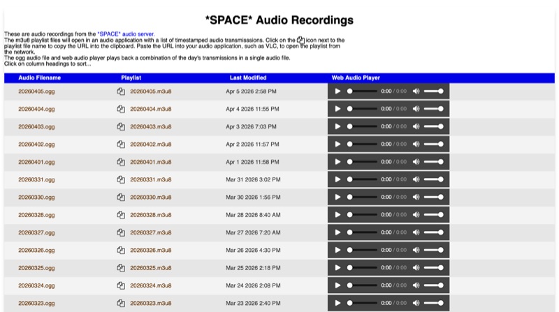 The *SPACE* Amateur Radio over Internet Protocol (RoIP) system offers public audio transmissions from NASA Mission Control and astronauts, primarily for educational purposes. This service streams NASA public media sources, including *Artemis II* and the ISS public audio channel 2 feed, which predominantly features English communications. Astronaut activities on the ISS typically occur between 0700 UTC and 19:00 UTC, with transmissions most common during early mornings USA time, alongside special events such as launches or spacewalks. Users can connect to the live stream via EchoLink to the *SPACE* conference, via IRLP to the 0100 experimental reflector, or via Allstar to node 516221. EchoLink connections utilize the GSM CODEC, while IRLP and other connections default to uncompressed or u-law CODEC. The service notes that long periods of silence are common, and NASA audio sources can be periodically unavailable or noisy. Daily recordings of these transmissions are published at space.rfnet.link/recordings/, available as .ogg audio files for direct playback or .m3u8 playlist files for network streaming in applications like VLC. Each playlist file provides a list of timestamped audio transmissions, allowing users to review specific segments of interest.
 -
 This project introduces the Loggi, a hybrid antenna merging the wide frequency coverage of log-periodic dipole arrays (LPDA) with the high gain and front-to-back ratio (F/B) of Yagi antennas. Traditional LPDAs span broad frequencies with moderate gain and low VSWR, while Yagis provide high gain and F/B over narrow bands. By analyzing high-Tau LPDA designs, it was found they could nearly match the gain of VHF/UHF Yagis while maintaining excellent patterns, F/B, and front-to-rear ratios (F/R). Optimizing specific elements for target frequencies (e.g., 144.1 MHz) led to the Loggi, which uniquely features all driven elements without passive directors or reflectors. This design effectively functions as a narrowband optimized LPDA, with front elements acting like Yagi directors and rear elements like Yagi reflectors, thus enhancing gain and directional characteristics while retaining broad frequency versatility.
 -
 This project details the design and construction of a Spider Quad antenna for HF bands (20m, 17m, 15m, 12m, and 10m). The boomless structure optimizes driver and reflector spacing, enhancing performance. Tuning and impedance matching were refined using antenna analyzers and a 1:2 balun. Final tests confirmed excellent SWR and gain, making this an efficient solution for top performance DXing.
 -
 The treehouse project is an YSF reflector with multiple rooms. You can change rooms via the dashboard or DGID on your radio. See radio model on the dashboard, Supports VW and DN mode,Change rooms on dashboard
 -
 Details the construction of a portable 6-meter 4-element quad antenna, specifically designed for VHF and Field Day operations. The design emphasizes portability and rapid field assembly, utilizing a 10-foot boom, #12 bare wire elements, and fiberglass electric fence post spreaders. It presents specific dimensions for reflector, driven element, and directors, including spreader lengths, circumferences, and corner marks, all derived from a G0KSC design and modeled in EZNEC. The resource outlines the fabrication of synthetic lumber hubs that allow post-assembly adjustments along the boom, and describes spreader clamps made from ¾” OD fiberglass rod, drilled and tapped for 8-32 nylon thumbscrews to secure element wires. It provides instructions for reducing spreader ends to 0.370” OD for proper fit and details the assembly of the boom from two 1½” OD x 6’ aluminum tubes. Performance data from EZNEC modeling indicates a gain of 10.25 dBi (8.1 dBd) and a 20 dB F/B ratio at 50.150 MHz, with SWR values of 1.08, 1.09, and 1.11 at 50, 50.15, and 50.5 MHz respectively. The document includes a field test report from Field Day 2010, where the antenna was deployed at 21 feet, showing an SWR resonance 200 KHz below EZNEC predictions. It notes successful 5-watt QSOs into New York and Canada from Tennessee, highlighting the antenna's excellent directivity and gain compared to a 4 dBd Moxon. The antenna breaks down into easily transportable components, including two 5’ boom sections, a 3’ boom connector, 16 spreaders, and four element/spreader clamp assemblies.
 -
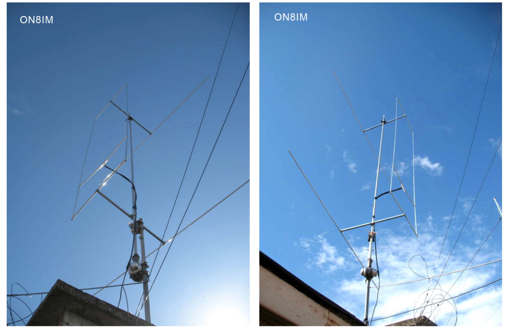 Explores the addition of a reflector to the traditional Hentenna design for 6m band, providing construction insights, performance comparisons, and modeling data
 -
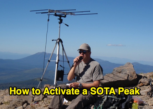 Outlines the essential steps for successfully activating a **Summits on the Air (SOTA)** peak, providing a structured approach for amateur radio operators participating in this popular award program. It details crucial pre-activation planning, including navigating the SOTA website, setting up a SOTA Data account, and consulting the **Association Reference Manual (ARM)** for specific regional rules and peak information. The guide also covers using mapping resources like adventureradio.de and lists ofjohn.com to identify suitable summits and check access conditions. The document emphasizes safety during the activation, advising operators to monitor weather, carry rain gear, and plan ample time for the ascent and descent. It specifies the **4-QSO minimum** requirement within the Activation Zone and recommends calling "CQ SOTA" on traditional QRP or VHF calling frequencies. The guide also suggests using local 2m FM repeaters for safety communications and spotting, while clarifying that repeater QSOs do not count for SOTA points. Post-activation activities include submitting logs to sotadata.org.uk, uploading trip reports to share experiences with future activators, and promoting SOTA participation on various reflectors. The guide highlights the program's appeal through its awards system for both activators and chasers, encouraging new participants in North America.
 -
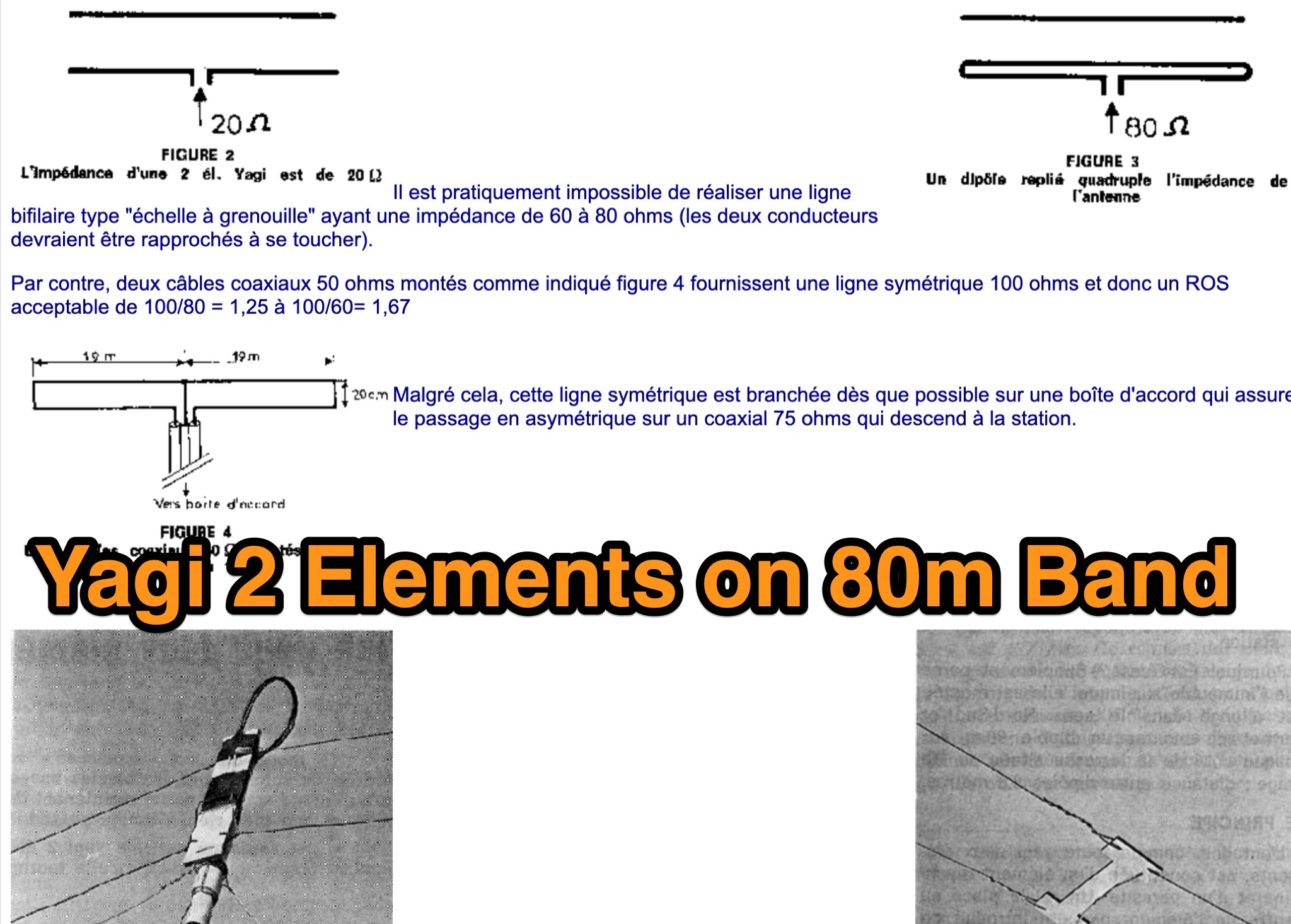 This article from the July 1976 issue of Radio REF discusses the trend of large antennas for ham radio operators on the low bands. It specifically focuses on a Yagi 2 element antenna for the 80m band, detailing its construction and functionality. The author explains how the antenna can be switched between directing signals towards the West or East using a switch at the station. The article also provides technical details on the lengths of the director and reflector elements, and how they impact the antenna's performance. A useful resource for hams looking to build or understand Yagi antennas for the 80m band.
 -
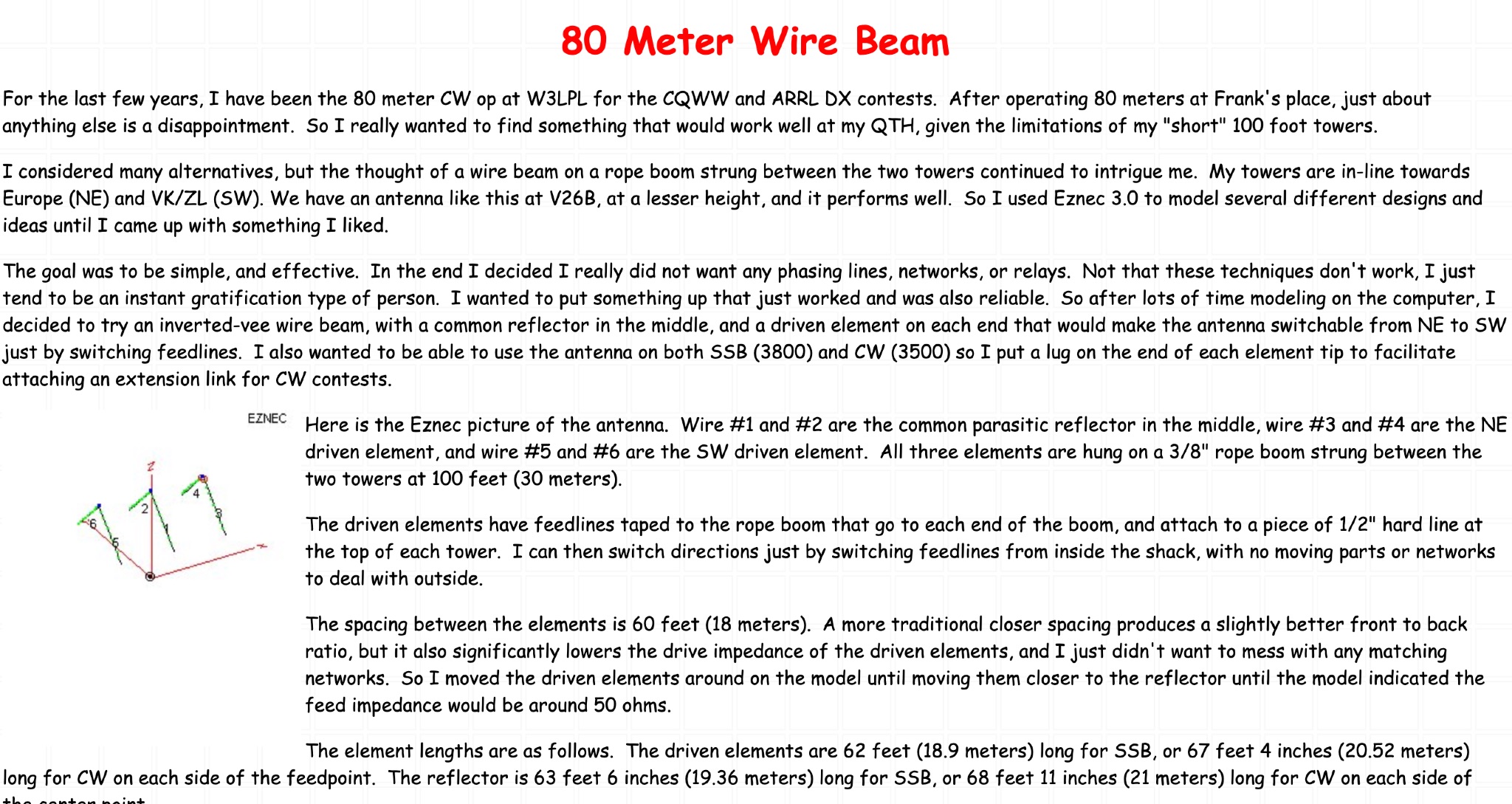 This paper presents an 80 meter wire 3-element beam antenna in an inverted-V configuration, designed for limited-height towers. Using EZNEC modeling, the antenna features a central parasitic reflector and two switchable driven elements at each end, enabling NE/SW coverage without moving parts or networks. Element lengths are optimized for SSB (3.8 MHz) and CW (3.5 MHz) operation, with a 50 Ω feed and rope-supported boom. The design delivers high gain, effective takeoff angles, and excellent reception, confirmed in real-world DX contest operation. Its simplicity, reliability, and ease of construction make it ideal for operators seeking performance without complex matching systems.
 -
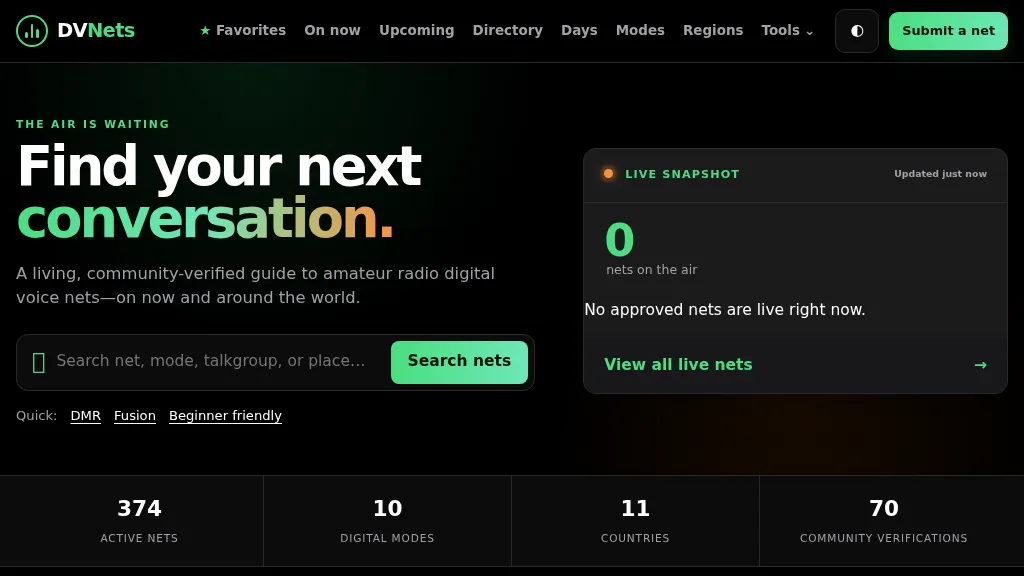 For amateur radio operators seeking to engage in digital voice communications, DVNets provides a centralized, community-verified directory of active nets. It organizes net schedules by **digital mode**, day, region, and access details, covering systems such as DMR, BrandMeister, D-STAR, System Fusion (YSF/C4FM), AllStar, EchoLink, M17, P25, NXDN, Wires-X, IRLP, and FreeDV. The platform offers specific connection information including talkgroups, reflectors, and rooms to facilitate participation in these digital voice activities. DVNets currently lists 374 active nets across 10 digital modes and 11 countries, with 70 community verifications ensuring accuracy. Users can browse nets by specific digital voice mode, view a weekly schedule, or explore listings by region, including the United States (142 nets), Canada (38 nets), and the United Kingdom (27 nets). The directory also features a "Happening soon" section, displaying nets active or starting shortly in the user's local timezone.
 -
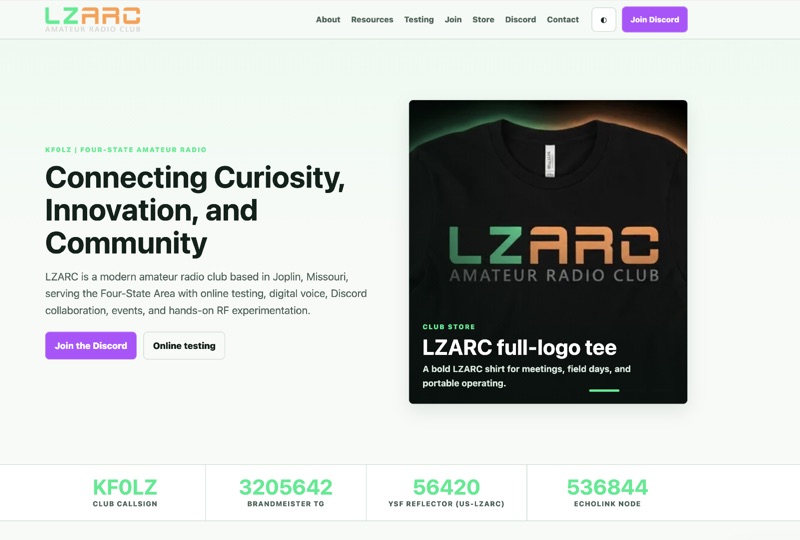 The LZ Amateur Radio Club (LZARC) operates with the club callsign **KF0LZ** and utilizes BrandMeister Talkgroup 3205642, YSF Reflector 56420 (US-LZARC), and EchoLink node 536844 for digital voice communications. This club, based in Joplin, Missouri, provides online FCC amateur radio license testing for Technician, General, and Amateur Extra class licenses, facilitating entry into the hobby. LZARC actively promotes hands-on RF experimentation, mesh networking with **Meshtastic**, and participation in **Parks on the Air** (POTA) activations. LZARC hosts regular events including the N0NMS Youth Net on 145.350 MHz (PL 91.5), the LZMesh Net on the LZMesh Meshtastic Channel, and the LZARC Digital Voice Net (CHAOS Net) via BrandMeister TG 3205642. The club maintains an active Discord server with over 300 members for daily conversations, project discussions, and quick support. Recent updates highlight member upgrades and participation in local hamfests, demonstrating a focus on community engagement and operator development across Missouri, Arkansas, Oklahoma, and Kansas.