Search results
Query: 70 MHz
Links: 191 | Categories: 3
-
 A W8JK/Moxon antenna variant with 400cm long monopoles is detailed, demonstrating a **1dbd** gain improvement over the traditional Open-Folded W8JK. This design, relying on the _Moxon principle_, achieves higher radiation impedance, leading to increased antenna efficiency and reduced losses. The article includes VNA output data for various HF bands, showing impedance characteristics from 10.1 MHz to 50.1 MHz, and provides NEC model wire definitions for the antenna structure. Field tests performed by F6IIV, Marc, compared his W8JK Moxon style antenna against a Cobweb antenna at the same height. Results indicated the W8JK Moxon variant provided a **6dB** (1 S-meter point) advantage on most bands from 20m to 10m, and a significant 10dB (1.5 S-meter points) advantage on 15m. The antenna features a 2.70m boom and a turning radius of less than 3 meters, making it suitable for limited space installations while maintaining bi-directional performance on most bands.
 -
 10 Elements Cross-Yagi Antenna for 433 MHz. The base of the 10el antenna is the recalculated RA6FOO antenna.Circular polarization is realized - by a phasing quarter-wave line, matching of horizontal and vertical polarization antennas
 -
 Constructing a directional antenna for VHF operations, particularly for 2-meter band contests or local communication, often involves balancing performance with ease of build. The Moxon rectangle, a compact two-element beam, offers a good front-to-back ratio and gain in a smaller footprint compared to a Yagi, making it suitable for portable or temporary setups where space is limited. This design typically uses a driven element and a single reflector, bent into a rectangular shape to achieve its unique radiation pattern. The article details the construction of a 2-meter Moxon antenna, specifically for 144 MHz, utilizing readily available materials like PVC pipe for the frame and copper wire for the elements. It outlines the dimensions for the driven element at 970mm and the reflector at 910mm, with a spacing of 140mm between them, and a 50mm gap at the element ends. The feedpoint is a direct 50-ohm connection, simplifying matching requirements. The project includes a parts list, a basic diagram illustrating the element layout and dimensions, and photographs of the completed antenna. The author notes the antenna's performance during a QRP contest, achieving contacts up to 100km with 5 watts, demonstrating its effectiveness for low-power VHF work.
 -
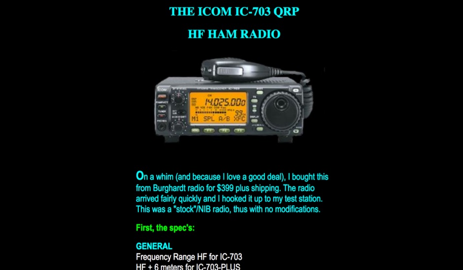 A review with early observations and technical data specifications of the Icom IC-703 QRP HF+50 MHz transceiver
 -
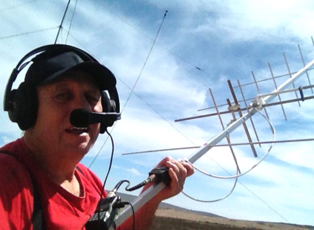 Construction of an antenna for experimental satellite communication, 8el. (435 Mhz) x 4el. (145 Mhz) Satellite Yagi crossed. No difficulty to built this antenna. Except the gamma match. that requires a little more attention
 -
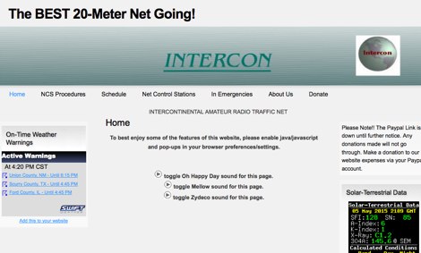 The Intercontinental Amateur Traffic Net (Intercon) operates daily on 14.300 MHz, providing a platform for emergency communications and facilitating third-party traffic among amateur radio operators. Established in 1960, the net aims to foster goodwill and friendly relations within the ham community. It operates from 0700 to 1200 Eastern Time, with a focus on monitoring emergency traffic while encouraging operators to maintain a distance of at least 5 kHz to avoid interference. All licensed General Class operators and above are welcome to check in, using standard phonetics for clarity. The net features rotating Net Control Station (NCS) operators every hour, ensuring a diverse range of voices and experiences. Operators are encouraged to provide relays and assist with emergency traffic when necessary. While there is currently no membership for non-NCS operators, opportunities exist for those interested in becoming NCS operators. The net emphasizes professionalism and courtesy, making it a valuable resource for both emergency communications and casual check-ins.
 -
 A ham radio home made preamplifier for 50 MHz and 70 MHz bands
 -
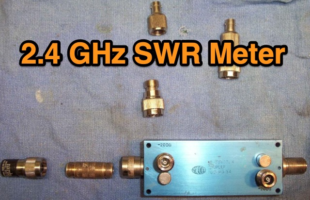 This is a simple 2.4 GHz SWR meter which is based around surplus microwave hardware which can be easily found. The main component is a MECA -20/-20 dB Directional Coupler which has a frequency range of approximately 700 MHz to 2.5 GHz.
 -
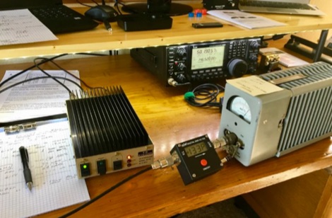 TE Systems 0510G 50 MHz meter amplifier set up for 10 watts in and 170 watts out.
 -
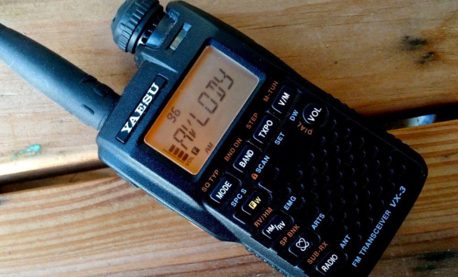 Review of Yaesu VX-3R 2 m/70 cm FM transceiver. Receives 0.5-999Mhz AM/FMN/FMW, Transmits 144-148 and 430-450Mhz VHF/UHF FM.
 -
 This multiband transverter project features power output at 13,8V 50MHz 15W, 70MHz 10W, second harmonic < 65dBc. Single N connector of antenna, suitable for a dual band Yagi. Article include Block Diagram for Dual Transverter and low pass filters
 -
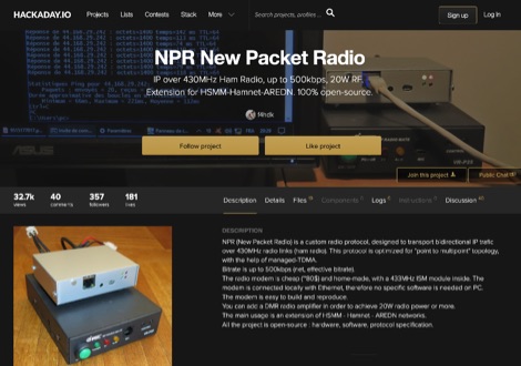 NPR (New Packet Radio) is a custom amateur radio digital protocol, designed by F4HDK to transport bidirectional IP trafic over radio links on the 70cm band. This IP protocol is optimized for point-to-multipoint topology, with the help of managed-TDMA. Bitrate is up to 500kbps. Home Made modem has a built-in ethernet port to connect to PC. To boost power a DMR amplifier is required to reach 20W. This project is an extension of HSMM - Hamnet - AREDN networks
 -
 Presents a detailed construction guide for a 9 dB, 70cm collinear antenna, utilizing readily available _RG58/U_ coaxial cable and PVC pipe for housing. The resource outlines the critical calculations for ½ wavelength sections at 444 MHz, incorporating the coaxial cable's velocity factor of 0.66, which yields a section length of 223 millimeters. It specifies the preparation and soldering of eight such half-wavelength sections, each cut to 231mm to allow for trimming, forming the core of the array. Further instructions detail the integration of a ¼ wave element (169mm #16 solid wire) at the top and a ¼ wave aluminum tube (160mm, 5/16 inch) at the bottom, crimped to the feed point's braid. The guide also addresses RF common mode current suppression by suggesting the use of _FT50-43_ toroids on the feedline. Final assembly steps cover mounting the antenna within ¾" PVC pipe using a wooden dowel, waterproofing connections, and initial SWR checks. The article also discusses scaling the design for different element counts and other VHF/UHF bands.
 -
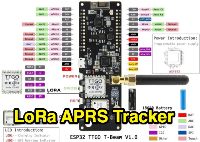 Setting up a Lora APRS tracker using the ESP32 Lora32 TTGO-T T-Beam 433/470Mhz Module.
 -
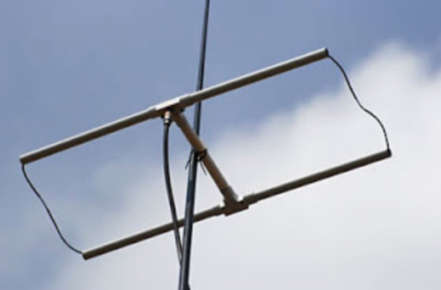
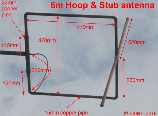 Omni-directional mixed polarisation antenna for 50MHz & 70MHz. This is a simple Halo and Stub antenna which provides an omni-directional radiation pattern with mixed polarisation, which I built for use with the SUWS WEB SDR
 -
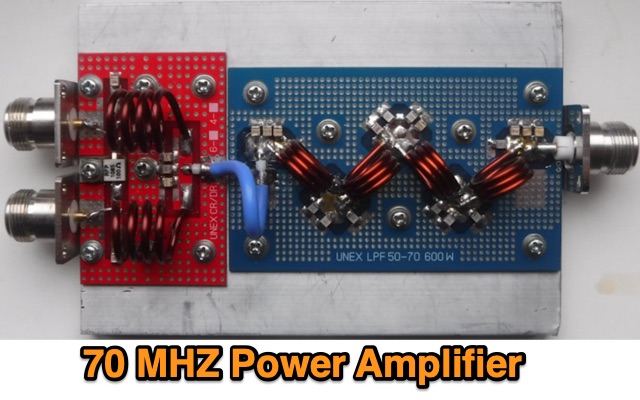 This PA has been designed by Sergey EX8MLE and uses three Mitsubishi RD100HHF1 FETs, Frequency Range 70 to 72 MHz
 -
 The 222 MHz Transverter project, based on Zack Lau's (W1VT) original July 1993 QEX magazine design, provides an IF of 28 MHz for both transmit and receive paths. Rick Bandla (VE3CVG) contributed supplemental notes and construction details, including modifications to achieve 10 mW output power from an initial 4 mW PEP. The design incorporates three distinct boards: a Local Oscillator (LO), a Transmitter (Tx), and a Receiver (Rx), with an estimated parts cost of just over $150 CDN, significantly less than commercial kits. Construction involves both through-hole and surface-mount components, with specific guidance on mounting MAV and MAR devices, grounding techniques, and component selection. The project details include parts lists, schematics for the LO, Tx, and Rx, and board layouts. Troubleshooting advice emphasizes sequential testing, starting with the LO, then Tx, and finally Rx, using a 194 MHz and 222.100 MHz capable FM handheld for signal tracing. Further enhancements are discussed, such as an optional Tx driver stage to boost output to 100 mW and the potential modification of a Motorola Maxor 80 PA for 222 MHz SSB/CW operation. The resource also covers practical aspects like power attenuation pads for IF radios (e.g., FT817) and considerations for enclosure design, including repurposing a Maxor 80 case. Performance reports indicate successful 70 km contacts with only 4 mW output.
 -
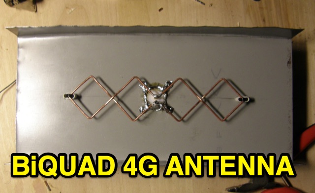 This is basic instructions for homemade 4G Antenna working on 2600 MHz UMTS featuring 13 14 dBi gain. This antenna is desigend to resonate on microwave frequencies in two segments from 2500 to 2570 MHz for Uplink, and from 2620 to 2690 MHz for Downlink.
 -
 This is a power amplifier project for a RF 600W 1.8 MHz to 70 MHz linear amplifier including a Low Pass Filter. Projects includes schematics, pictures, PCD design, fans details, note on PA ferrite chokes and assembling instructions
 -
 A homemade quarter wave ground plane anntenna for 4 meters band.
 -
 A homebrew spectrum analyzer, the Specan, provides a crucial measurement capability often missing from the typical amateur radio shack, allowing for detailed analysis of RF signals up to 70 MHz. This double-conversion superheterodyne receiver design incorporates 112 MHz and 12 MHz intermediate frequencies, utilizing an _Si570_ as the local oscillator for fine tuning down to 1 Hz steps. It offers two resolution bandwidths: 300 KHz for broad spectrum sweeps and 1 KHz for precise close-in distortion measurements, achieving an 80 dB spur-free dynamic range at 1 KHz resolution. The project, a reboot of the classic _W7ZOI/K7TAU_ design from November 1998 QST, integrates an _Arduino_ microcontroller for controlling the Si570, managing a front-panel LCD, and communicating with a PC for spectrum plotting. This approach significantly reduces cost compared to commercial units, making advanced RF diagnostics accessible to homebrewers. The Specan can measure carrier suppression, VFO cleanliness, antenna VSWR, transmitter harmonics, and filter passband shapes, providing insights beyond what an oscilloscope or frequency counter can offer. Construction emphasizes modularity and careful shielding, with each stage built and tested individually on unetched copper clad board. The design includes detailed instructions for integrating the Arduino, building the Si570 oscillator, and aligning the various modules, often using the Specan itself for calibration. It requires a well-regulated linear power supply and can be built with common tools and readily available components, making it a practical and rewarding endeavor for those looking to enhance their RF test bench.
 -
 Discover the success story of creating a 4-meter Delta Loop antenna, ideal for improving radio communication. This horizontally polarized antenna offers efficient performance when mounted at VHF heights, catering to both HF and VHF characteristics. A simple, DIY project suitable for portable setups, providing versatile options for radio enthusiasts.
 -
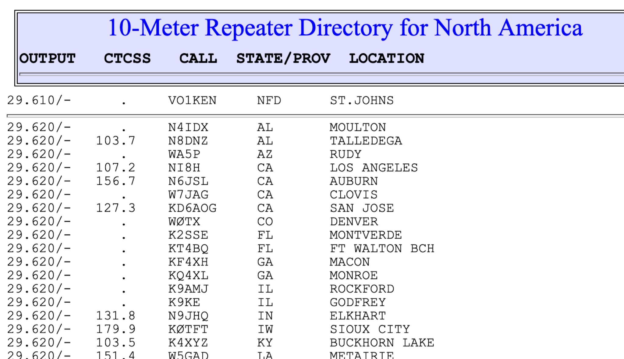 This page show a list of repeaters in north america transmitting from 28 MHz to 29 MHz. The most of them are in the 29.620 to 29.700 frequency range. Some repeaters may be active and on the air while others may not
 -
 This is a plan for an optimized element UHF Yagi Antenna for UHF Bands featuring a 9dBd forward gain, a 13 dB front-back ratio, and a bandwith of 10 MHz on the 430-440MHz range.
 -
 Manufacturer of 50MHz, 70MHz, 144MHz, 222MHz, 432MHz, 900MHz or 1.2GHz transverters and VHF UHF amplifiers
 -
 Chavdar Levkov, LZ1AQ, presents an experimental comparison of small wideband magnetic loops, building on his previous work on wideband active small magnetic loop antennas. His research focuses on increasing loop sensitivity by maximizing the short-circuit current, which is directly tied to the "loop factor" M = A/L, where A is the equivalent loop area and L is its inductance. Levkov's methodology involves reducing inductance and increasing area through parallel or coplanar crossed (CC) configurations, comparing these designs against a reference single quad loop of 1 m2 area. Experimental verification included testing three distinct loop types: a simple quad loop, two coplanar crossed (CC) loops, and eight parallel loops, all designed to have a total geometric area of 1 m2. Measurements were conducted at 1.8, 3.5, 7, and 10 MHz using a small transmitter 270 meters away, with a Perseus direct sampling receiver for precise signal level assessment. The results consistently showed that CC loops, particularly Loop 5 (two CC circular loops with 1.44 m2 total area), yielded significantly higher currents, up to 9.1 dB over the reference loop at 3.5 MHz, validating M as a reliable predictor of loop sensitivity. Numerical simulations using MMANA further corroborated the experimental findings, demonstrating an almost perfect correlation between the calculated M factor and the induced loop current for 15 different loop models. Levkov concludes that CC loops offer superior sensitivity for a given loop area, while parallel loops are advantageous for minimizing physical volume. Practical recommendations suggest using loops with an M factor greater than 0.5 uA/pT for quiet rural environments, and he provides a spreadsheet tool, WLoop_calc.xls, to aid in optimizing loop configurations for specific operational needs.
 -
 This resource details the construction and performance of a compact broadband magnetic loop antenna designed for portable receiving applications with devices like the _ATS MiniRadio_. The antenna utilizes approximately 3 meters of 0.5–1 mm copper wire wound in two turns on a rhomboidal wooden frame, measuring 50 cm by 70 cm. It connects via a modified 9:1 unun, where the primary center tap is isolated from ground to improve common-mode noise rejection. The design provides untuned operation across a frequency range from the longwave band up to approximately 25 MHz. Performance characteristics include observable directivity for noise suppression and the ability to connect directly to a radio or via a 50 coaxial cable for remote operation. The article specifies the unun's 3:1 turns ratio and its SMA output for connectivity. The methodology focuses on practical construction and observed reception quality.
 -
 The resource details the construction of a 433 MHz LoRa APRS iGate and a tracker, both built around _TTGO T-Beam v1.1_ microcontroller boards. Each board integrates an OLED screen, WiFi, GPS, and an SMA antenna connector, powered by an 18650 3.7 V lithium-ion battery or microUSB. The iGate operates on 433.775 MHz, with its status verifiable on aprs.fi, demonstrating practical implementation of LoRa-based APRS solutions. The methodology involves programming the modules using Visual Studio Code with the PlatformIO plugin. This process loads the necessary firmware and a JSON configuration file, which includes the operator's callsign and WiFi credentials for the iGate. The guide emphasizes the ease of programming and provides specific steps for configuration. Initial testing of the iGate and tracker, including smart beaconing configuration, is documented. The low power output of approximately 200 mW from the LoRa board's transmitter is noted, with suggestions for range extension through improved antennas or RF amplification. The author, N4MI, plans to deploy a higher-gain 70cm antenna for the iGate.
 -
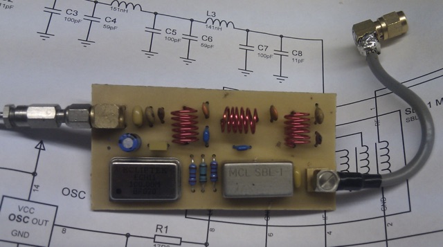 This article describes an HF upconverter for the FunCube Dongle Pro. Designed for radio amateurs, the converter extends reception capabilities to lower frequencies (0 Hz to 30 MHz) by mixing them with a higher oscillator frequency (100 MHz). This translates the desired signal into a range detectable by the FunCube Dongle (64 to 1,700 MHz). Key components include a double-balanced mixer and a low-pass filter to suppress unwanted signals. The project provides schematics, filter specifications, and design considerations for construction.
 -
 The Pikes Peak Radio Amateur Association (PPRAA) serves as an ARRL Special Service Club, providing a calendar of events and activities for its members and the wider amateur radio community. The resource details upcoming events such as the USS Pueblo Memorial Museum Ships Weekend activations, a Cubical Quad Antenna Workshop, LARCFest, and various hamfests including Dayton Hamvention and Duke City Hamfest. It also lists on-air activities like a FreeDV digital voice mode event on 10 meters, a Black Friday Simplex Event on 2M and 70cm, and a 10m event for Technician class operators, emphasizing SSB privileges from 28.300 to 28.500 MHz. The PPRAA's event schedule includes educational opportunities like a Technician Class and a Soldering Workshop, alongside social gatherings such as the PPRAA Picnic and Car Show. Past event summaries highlight successful activities like the 2024 Megafest Raffle, Winter Field Day, and multiple fox hunts utilizing frequencies like 147.420, 147.480, and 147.540 MHz. The club actively supports POTA activations, exemplified by their AF0S park activation at Cheyenne Mountain State Park, and participates in historical commemorations like the USS Pueblo Memorial operations, demonstrating a broad engagement across various amateur radio facets.
 -
-
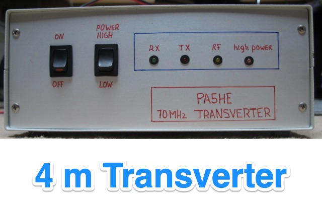
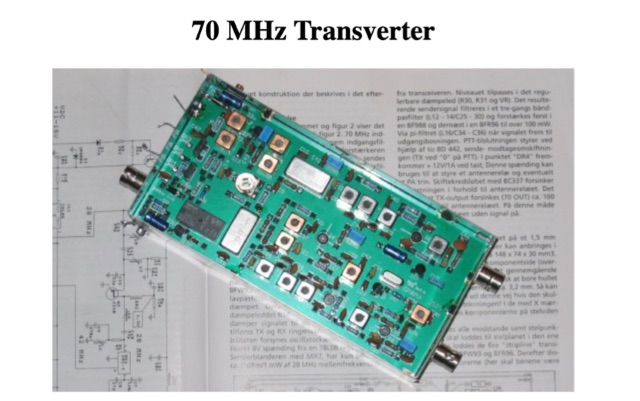 This page gives a brief description of a 70 MHz transverter that has been published in the Danish amateur radio magazine "OZ." This way hams outside Denmark may also benefit from the design.
 -
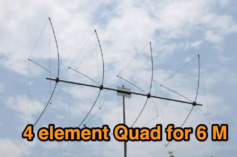 Details the construction of a portable 6-meter 4-element quad antenna, specifically designed for VHF and Field Day operations. The design emphasizes portability and rapid field assembly, utilizing a 10-foot boom, #12 bare wire elements, and fiberglass electric fence post spreaders. It presents specific dimensions for reflector, driven element, and directors, including spreader lengths, circumferences, and corner marks, all derived from a G0KSC design and modeled in EZNEC. The resource outlines the fabrication of synthetic lumber hubs that allow post-assembly adjustments along the boom, and describes spreader clamps made from ¾” OD fiberglass rod, drilled and tapped for 8-32 nylon thumbscrews to secure element wires. It provides instructions for reducing spreader ends to 0.370” OD for proper fit and details the assembly of the boom from two 1½” OD x 6’ aluminum tubes. Performance data from EZNEC modeling indicates a gain of 10.25 dBi (8.1 dBd) and a 20 dB F/B ratio at 50.150 MHz, with SWR values of 1.08, 1.09, and 1.11 at 50, 50.15, and 50.5 MHz respectively. The document includes a field test report from Field Day 2010, where the antenna was deployed at 21 feet, showing an SWR resonance 200 KHz below EZNEC predictions. It notes successful 5-watt QSOs into New York and Canada from Tennessee, highlighting the antenna's excellent directivity and gain compared to a 4 dBd Moxon. The antenna breaks down into easily transportable components, including two 5’ boom sections, a 3’ boom connector, 16 spreaders, and four element/spreader clamp assemblies.
 -
 The tri-band trapped delta loop antenna design operates on 80 meters (3.5–4 MHz), 40 meters (7–7.3 MHz), and 30 meters (10.1–10.15 MHz) using a single triangular wire loop. This configuration eliminates the need for an external antenna tuner or band-switching relays. The antenna's physical perimeter, approximately 270 feet, establishes 80M as the fundamental band, with specific trap placements enabling resonance on 40M and 30M. Trap design and placement are critical, with 30M traps positioned inboard of 40M traps within the horizontal element. Each slant leg measures approximately 80 feet. The resource references foundational information from the _ARRL Antenna Handbook_ and _ON4UN’s Low Band DXing_ regarding full-wave loop behavior and feedpoint impedances. The project aims to provide multi-band HF operation from a single, fixed antenna structure.
 -
 This project documents the construction of a coaxial 50 MHz notch filter to eliminate inter-band interference between 50 and 70 MHz transceivers. Using RG-213 coax and based on quarter-wave stubs, the filter achieved a 44 dB attenuation at 50.060 MHz while maintaining low insertion loss on 70 MHz. A dual-stub design broadened the notch response and minimized attenuation on 70 MHz to 0.2 dB. Fine-tuned using an FA-NWT network tester and Elecraft XG3 signal source, the filter effectively resolved interference for seamless dual-band operation.
 -
 The RXC70/10 is a sensitive 70 MHz to 10-meterband converter using the Philips SA602 mixer IC. It operates with high stability and low noise, converting 70–72 MHz signals to 28–30 MHz for general coverage receivers. The compact, low-power design (15mA) supports various modulations and uses. Its versatility makes it suitable for amateur radio applications with proper tuning and antenna setup.
 -
 The FF-501DX LPF, a high-performance VHF and 10m filter, was obtained at a friend's SK sale. After becoming more active on 10m, the author reexamined the LPF and discovered it to be of high quality. The filter's efficiency was outstanding and the return loss/VSWR was better than estimated. The LPF was connected to a Bird 50R dummy load to evaluate insert loss, cutoff, attenuation over 70MHz, and return loss. The original specifications were found in an old radio magazine, along with a link to the original one-page information sheet. Comparing the results to the original specs confirms the LPF's quality.
 -
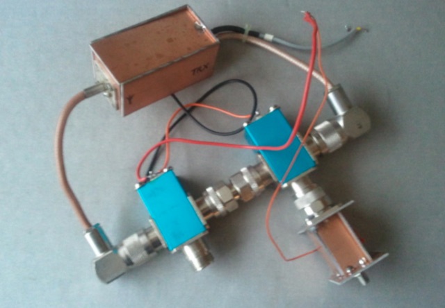
 SAT filters ensure effective full-duplex satellite QSOs by mitigating interference between 145 MHz uplink and 435 MHz downlink signals. Custom coaxial and SMD-based filters address transmitter harmonic interference and improve receiver isolation, achieving over 70 dB suppression in the undesired band. Designed for simplicity, these filters maintain optimal VSWR and are housed in shielded brass enclosures. Practical implementations with Yagi antennas demonstrate compatibility with SDR systems, enabling seamless communication even in challenging satellite conditions, such as low-elevation passes and DX pile-ups.
 -
 The 4m Slim Jim antenna project provides a construction guide for a low-cost, high-performance aerial designed specifically for the 70 MHz FM band. This design achieves a 1:1 SWR across the 4m FM band with straightforward adjustment of the feed point, utilizing RG-58 coax. Its low angle of radiation contributes to effective signal propagation. Construction involves using plastic knitting needles as spreaders and a telescopic fishing pole for support, with components secured using two-part epoxy. Annealed bare single-core copper wire forms the radiating element. The setup process includes raising the antenna at least 3 meters above ground for tuning, adjusting the RG-58 feed point for optimal SWR, and then soldering connections. Waterproofing is achieved with yacht varnish. The design emphasizes low wind resistance for durability, making it suitable for exposed outdoor installations. A PDF construction diagram is available to supplement the written instructions.
 -
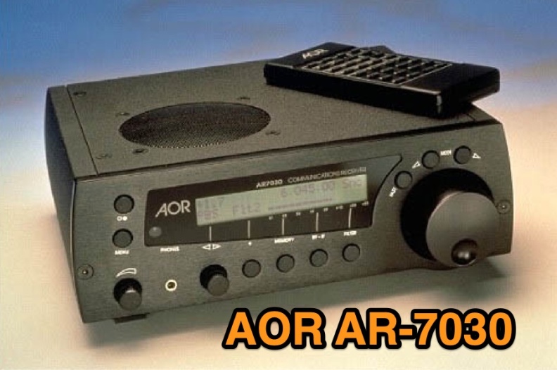 Examines the AOR AR-7030 communications receiver, detailing its technical specifications and operational characteristics. The resource describes its compact design, CNC machined aluminum cabinet, and a frequency range spanning 0-32 MHz. Key features include a ceramic metal cased 4 kHz AM filter, with typical bandwidths of 2.2 kHz, 4.0 kHz, 5.3 kHz, and 9.5 kHz, alongside 400 memory channels and multi-timer functionality. It emphasizes the receiver's high-quality components and a design philosophy focused on reliable performance without superfluous features, making it a dedicated tool for serious listeners. The review assesses the AR-7030's performance within its price class, particularly for **medium wave** and **shortwave** reception. It provides insights into how the receiver's design choices, such as its robust construction and specific filter options, translate into practical listening experiences. The analysis highlights its suitability for users prioritizing signal clarity and operational stability over extensive, complex features, offering a clear perspective on its utility for dedicated DXers and broadcast listeners.
 -
 For amateur radio operators seeking resilient, off-grid communication, the _MeshCom_ firmware provides a robust solution for text-based messaging over a mesh network. Utilizing LoRa modulation and the APRS protocol, this firmware is designed for low-energy consumption and cost-effective hardware, primarily operating in the 70cm band. Nodes, identified by amateur radio callsigns, can send short text messages to all participants or directly to specific callsigns, functioning as repeaters to extend network reach. The system supports automatic status and position messages, with optional sensor data for WX-Data and Telemetry. MeshCom nodes can be configured as gateways to HAMNET or the internet, enhancing connectivity options. The project emphasizes a self-building and self-healing mesh network architecture, crucial for emergency communication scenarios. Operating frequencies include **433.175 MHz** (EU, USA, Africa), 439.9125 MHz (UK), and 433.925 MHz (Norway). The firmware is compatible with hardware platforms such as ESP32/LoRa modules, RAK-WISBLOCK, and ESP32-DEV4/E22-LoRa, offering a flexible deployment for various amateur radio applications.