Search results
Query: 4:1 balun
Links: 27 | Categories: 1
Categories
-
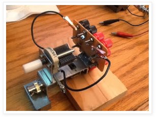
 I built a homebrew 75 meter Double Extended Zepp Antenna, And I needed a 4:1 Balun So I decided to Homebrew the Balun also. Here is how I did it!
 -
-
 Show diagrams, winding methods and tables of some 1:1 and 4:1 baluns for 1.8 - 30 MHz suitable for use up to 200W (400W peak) on systems using 50 or 75 ohm coaxial cable input where SWR should not exceed 1.6:1.
 -
 The 80-meter loop antenna, measuring 86 meters (282 feet) of wire, effectively operates across 8 HF bands from 80 through 10 meters, despite its length being a compromise for specific bands. This design prioritizes a "low enough" SWR across multiple bands, aiming for lower SWR values on higher frequencies due to increased feedline losses. A 200-ohm feedpoint impedance provides a workable SWR on every band, with feedpoint impedances ranging from 100 ohms for lower bands to 300 ohms for higher bands. Radiation patterns for the 80-meter loop, mounted at 15 meters high, show a maximum gain of 7.6 dBi at a 90-degree takeoff angle on 80 meters, and up to 12.9 dBi at a 10-degree takeoff angle on 12 meters. This configuration supports regional contacts on 80 meters and provides good DX performance on higher bands. Practical construction notes emphasize using robust supports like trees, ensuring wire slack with _egg insulators_ for wind resilience, and employing an oversized 2 kW 4:1 _balun_ to safely handle higher SWR conditions, even with 100W transceivers. Feedline losses are minimized using _LMR-400_ coax or ladder line, with power transfer efficiency between 80% and 95%. Antenna simulations were performed using _xnec2c_, and the provided NEC file is compatible with other NEC2 derivatives. The antenna is tunable on 6 of 8 bands with an internal ATU and all 8 bands with an external autotuner like the LDG AT-200 Pro.
 -
 Step-By-Step Construction of a 4:1 Current-Type Guanella Balun by W1CG
 -
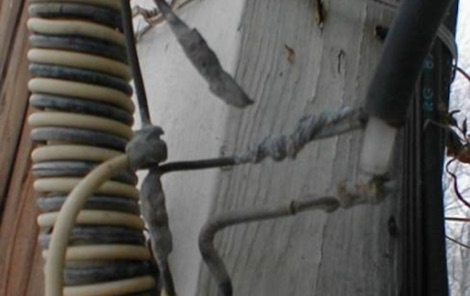
 The Windom is an Off-center wire multiband Antenna. The old version was fed just by a single-wire connected on 1/3 of antenna's overall length or with an open-line feeder (later versions). Here is another model with coaxial feeder, which is compatible with Solid States - 50 Ohm output transceivers .
 -
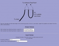 Online calculator for a 4 to 1 coax cable balun
 -
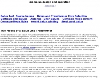 Real 4:1 Transmission Line Balun with Balanced Load
 -
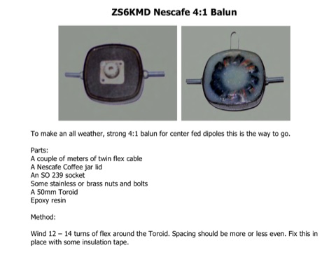 Making a 4:1 balun with a nescafe coffee jar lid and a toroid
 -
 Contruction manual to build a 4:1 balun, it has good performance from 160 through 10 meters.
 -
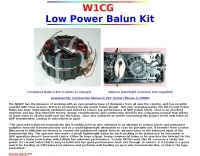
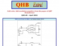 Build a Low Power 4:1 Balun , by Charles Greene, W1CG with full-color, full-resolution graphics from the pages of QRP Homebrewer
 -

-
 40mm diameter grey PVC pipe with a length of 9.5cm
 -
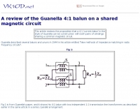 This article reviews the proposition that a 4:1 current balun in the style of Guanella can be constructed with both pairs of windings sharing a common magnetic circuit.
 -
 This is a popular antenna design as the performance is very good across the HF bands and requires little or no tuning. It is a dipole fed off center with a 4:1 current balun at the offset feedpoint. The antenna shown covers 80, 40, 20 and 10 meters with 15 meters and WARC bands
 -
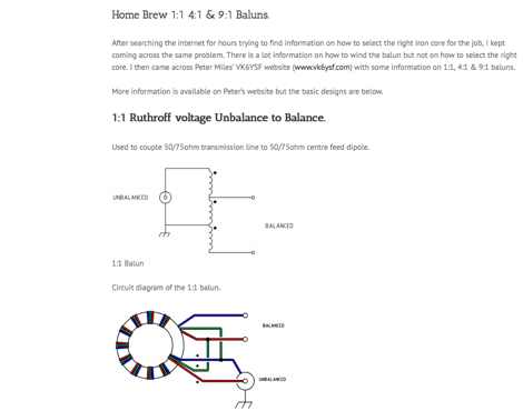 Circuit diagrams to homebrew different baluns by vk2awx
 -
 One point eight MHz to 30 MHz is the operational bandwidth for this 4:1 Ruthroff voltage balun, designed to interface an unbalanced T-Match network with a balanced antenna system. The project details the construction using a _T200-2_ powdered iron toroid core, tightly wrapped in PVC electrical tape for insulation, and wound with 17 double bifilar turns of 1.25mm enamelled copper wire. This outboard balun offers flexibility, allowing hams to trial various baluns based on antenna system and impedance characteristics, rather than integrating it directly into the tuner. The resource includes a schematic of the balun, a wiring diagram showing winding connections, and a table suggesting alternative toroid cores like the T80-2 or T400-2 with corresponding winding counts. Component sourcing is straightforward, listing items such as the _Amidon_ T-200-2 core, SO-239 connector, and a sealed polycarbonate enclosure from Jaycar. Performance evaluation was conducted using an _AIM 4170C_ antenna analyser, demonstrating efficient 1:4 voltage transformation across the specified HF spectrum. Further efficiency tests involved measuring RF power loss at various frequencies, revealing minimal loss—less than 0.7 dB from 3.6 MHz to 30 MHz, and only 2.0 dB at 1.8 MHz. These measurements, performed under ideal 50-ohm conditions, confirm the balun's effectiveness as a low-loss interface for multi-band antenna systems. The page also links to several other balun and unun projects, including 1:1 current and voltage baluns, and 9:1 voltage ununs, providing a broader context for impedance matching solutions.
 -
 Classical coax-fed, off-center-fed dipole, feeded with a 4:1 Guanella balun
 -
-
 Building a Windom HF Antenna. A PDF file presentation about homebrewing a windom antenna for the HF bands with formulas for 40 and 80 meters bands and step by step guide on making a 4:1 balun to feed the antenna.
 -
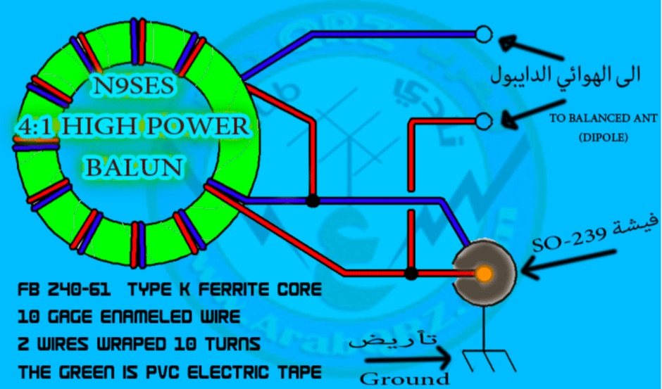 A home made 4:1 Ferrite QRO Bal-un with a FB 241-61 Type K
 -
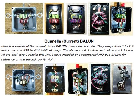 An interesting article on guanella baluns that cover several aspects of homebrewing 1:1 and 4:1 current baluns by KN9B
 -
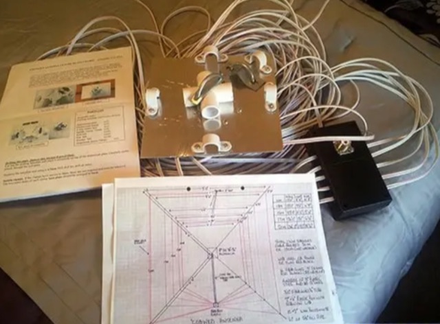 A home made cobweb antenna project made with easy to find parts 2-14 AWG speaker cables which are cut to 1/2 wavelength for each band and junction box with 4:1 Balun
 -
 This type of antenna is a popular antenna design as the performance is very good across the HF bands and requires little or no tuning. It’s a dipole fed off center with a 4:1 balun at the offset feed point. The antenna shown covers 80, 40, 20 and 10 meters. The formula can also be used to adjust the overall length to cover more or fewer bands and the resulting overall length. 160-10m, 80-10m or 40-10 meters depending on your available space. Other bands will require a tuner.
 -
 This article describes a multi-band antenna design for amateur radio enthusiasts by G3FEW. The antenna is designed to cover at least five HF bands with low SWR and without the need for an ATU. It is also designed to be easy to construct and adaptable for different locations. The antenna is a full-wave dipole with traps at the quarter-wave points. The traps are used to tune the antenna to different bands. The antenna can be fed with a 4:1 balun. The article includes instructions for building the antenna, as well as information on the theory behind its operation. The author also discusses the results of his tests with the antenna. This multi-band antenna is a well-designed and versatile antenna that can be used by amateur radio enthusiasts on a variety of bands. It is relatively easy to construct and can be adapted for different locations.
 -
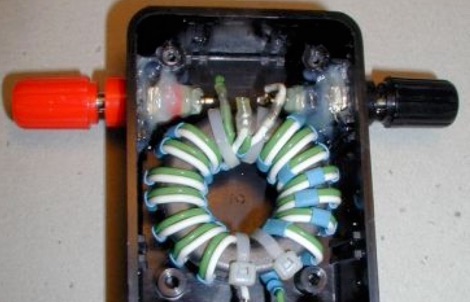
 This blog post details the construction and usage of a 4:1 current balun, using two FT240-31 ferrite cores and 12 bifilar turns. It clarifies common misconceptions about using 4:1 baluns with G5RV antennas and ladder-line to coaxial cable connections. M0PZT emphasizes the importance of proper measurements and the limitations of internal baluns in manual antenna tuners. Detailed instructions and considerations for winding and deploying the balun are provided, along with advice on choosing suitable cores and wire for various power levels and frequency ranges.
 -
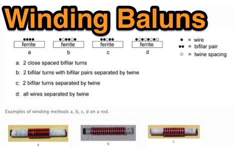
 This comprehensive three-part guide examines baluns (balanced-to-unbalanced devices) and their critical role in ham radio antenna systems. The author explains how baluns prevent common-mode currents on feedlines, which can distort radiation patterns and cause unwanted RF in the shack. Various balun types are analyzed, including coiled coax chokes, ferrite-core designs (W2DU), and toroidal-wound versions (Guanella/Ruthroff). Construction techniques for 1:1, 4:1, 6:1, and 9:1 current baluns are provided with practical guidance on wire selection, winding methods, and ferrite core properties. The article emphasizes that proper balun implementation is essential for optimal antenna performance, especially with directional arrays.