Search results
Query: building a power supply
Links: 8 | Categories: 1
Categories
-
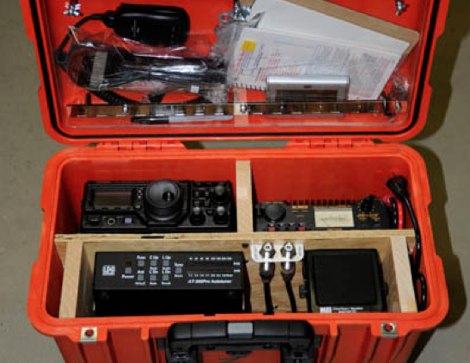 The best way to describe a go-box is a complete amateur radio station in a box. An example is described in this article. The project describes building a portable amateur (ham) radio station, known as a "go-box," housed in a durable orange Pelican case. The go-box contains all necessary radio equipment except for external power and antennae, which are carried separately. It includes items like a Yaesu transceiver, power supply, antenna tuner, speaker, and a clock. The case is designed for mobility and visibility, with a vertical layout to allow in-vehicle operation. Future upgrades might include cooling fans, an LED lamp, and built-in antennae for better functionality in various conditions.
 -
 The Collins 516F-2 is a heavy-duty power supply for the KWM-2/2A transceivers and the 32S-1,2,3 series of Collins transmitters.
 -
 A 4 AMP / 18V regulated power supply schematic, designed by _ON6MU_, provides a detailed circuit diagram for constructing a robust power source. The design focuses on delivering a stable 18-volt output at up to 4 amperes, crucial for powering various amateur radio equipment. This resource presents a clear visual representation of component interconnections, including rectifiers, filter capacitors, and voltage regulation stages, essential for DIY enthusiasts building their shack infrastructure. The schematic's clarity facilitates understanding the power flow and component roles within the circuit. This circuit design offers a practical solution for hams needing a reliable 18V supply, potentially useful for driving specific transceivers, amplifiers, or accessory circuits. While specific performance measurements or comparisons to other designs are not detailed, the schematic itself serves as a foundational blueprint. Builders can adapt or modify the _power supply_ to suit their particular needs, such as integrating overcurrent protection or fine-tuning the output voltage with adjustable regulators. The straightforward presentation makes it accessible for those with basic electronics knowledge to assemble and troubleshoot.
 -
 his article explores the construction of a PL519 tube amplifier, utilizing Ulrich L. Rohde N1UL's insights. Focusing on a modest 25W continuous output, the design ensures robustness with forced air cooling. The detailed breakdown covers input matching, screen grid voltage generation, bias adjustment, anode power supply, heater power supply, and monitoring circuitry, providing valuable guidance for ham radio enthusiasts.
 -
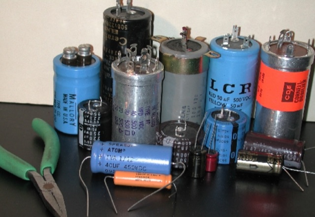 For low voltage applications, like cathode bypass capacitors, most vintage types have an axial configuration, which is less common today but still available. Electrolytic power supply caps likely constitute the single worst liability in old audio, radio and test equipment. Rap about Electrolytics, Reforming, Chassis-Mount Replacements, Under-Chassis Installation, Rebuilding Capacitors
 -
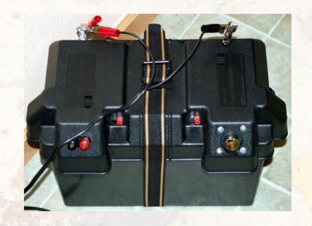 The article describes how to build a 12V emergency power supply for amateur radio stations. Starting with a basic jump-start system, the author upgraded it using a Group 27 deep-cycle battery and a 45W photovoltaic solar system, adding connectors and outputs for various devices. The system is portable, affordable (under $100), and capable of powering a station for 20 hours. The author emphasizes keeping batteries charged with a float charger and offers assistance to fellow club members interested in building their own power supply.
 -
 The project details the construction of a GM3OXX OXO transmitter, designed to accommodate **FT-243 crystals** using 3D-printed FX-243 holders from John KC9ON. It presents specific frequency adjustments, noting a 7030 KHz HC-49/s crystal could be tuned from 7029.8 KHz to 7031.7 KHz with an internal 45pF trimmer capacitor. The build incorporates a modified keying circuit to prevent oscillator run-on key-up and includes a TX/RX switch for sidetone via a connected receiver, with the transmitter output routed to a dummy load on receive. Practical construction aspects are thoroughly covered, including the process of cutting a rectangular opening in a diecast enclosure for the FT-243 socket and the selection of a **low-pass filter** (LPF) based on the QRP Labs kit, derived from the W3NQN design. The author achieved approximately 800mW output power from a 14.75V supply, measured with an NM0S QRPoMeter, using a 16.5-ohm emitter resistor in the 2N3866 final stage. The article also touches upon the potential for frequency agility across the 40M band using multiple FX-243 units with various crystals. The narrative includes a brief diversion into Bob W3BBO's recent homebrew projects, such as his Ugly Weekender MK II transceiver, highlighting the enduring appeal of classic QRP designs. The author reflects on the personal satisfaction derived from building RF-generating equipment, irrespective of DX achievements, and shares experiences of making local contacts with the 800mW OXO transmitter on 40 meters.
 -
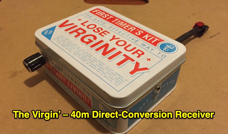 Demonstrates the construction of 'The Virgin', a **direct-conversion receiver** specifically designed for the 40m amateur radio band. This project, completed in February 2016, features a fixed operating frequency determined by a crystal oscillator, requiring a physical crystal change to alter the reception frequency. The design incorporates two integrated circuits and a power regulator, emphasizing simplicity with a single control knob. The author details the initial design, subsequent modifications to the front end, and troubleshooting steps addressing common issues like audio motorboating and power supply instability. The resource presents the final design of the receiver, reflecting the author's first experience building such a unit between December 2015 and February 2016. It offers practical insights into basic circuit construction and the iterative process of refining a homebrew radio project. The content is particularly relevant for those interested in fundamental receiver principles and hands-on **QRP** transceiver building.