Search results
Query: callsign series
Links: 5 | Categories: 0
-
 The HB9ABX RoomCap antenna document details the construction and performance characteristics of a compact HF antenna design. It presents a series of comparative field tests conducted between July and September 2005, evaluating the HB9ABX antenna against established designs like the Microvert MV-500, Cushcraft R5/R7000 verticals, and a 5-element DJ2UT Yagi beam. Specific test scenarios include mobile installations, rooftop deployments, and comparisons on 20m, 40m, 80m, and 160m bands, with signal reports from various European and DX stations. The resource emphasizes the antenna's small physical footprint and its claimed efficiency across multiple HF bands. Test results consistently show the HB9ABX antenna performing comparably to, and often outperforming, larger reference antennas in terms of received signal strength, with reported differences of 1 to 2 S-points (6-12 dB) in many contacts. Notably, a 20m DX test on July 26, 2005, indicated the 1.3m HB9ABX radiator yielded 2-3 S-points stronger signals than an R7000 vertical for US DX stations. An August 12, 2005, test on 40m highlighted the HB9ABX's superior signal-to-noise ratio in urban QRM, demonstrating 10-18 dB better performance than an R7000. The document includes specific callsigns, signal reports, and QTHs for each comparison, providing empirical data for the antenna's performance claims.
 -
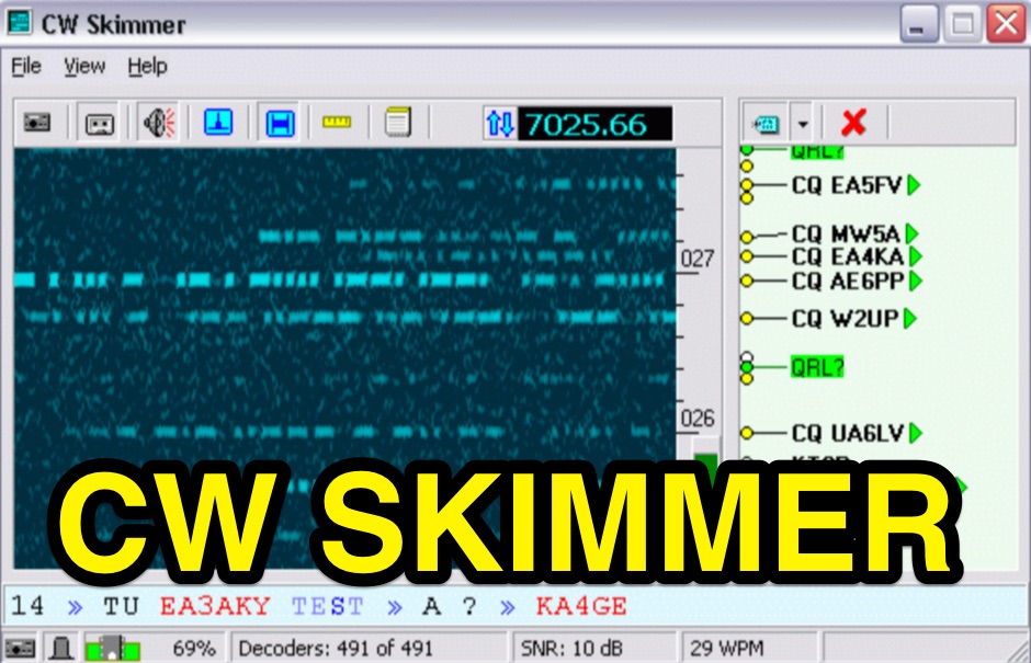 CW Skimmer 2.1 employs a high-sensitivity CW decoding algorithm based on Bayesian statistics, enabling simultaneous decoding of up to 700 CW signals within a receiver's passband on a 3-GHz P4 system when paired with a wideband receiver. The software features a fast waterfall display with sufficient resolution for visual Morse Code interpretation, automatically extracting and labeling callsigns on the waterfall traces. Extracted callsigns are exported as DX cluster spots via an integrated Telnet cluster server. The application includes a DSP processor with a noise blanker, AGC, and a variable-bandwidth CW filter, alongside an I/Q Recorder and player. It supports both 3 kHz radio passbands and wideband SDR receivers like SoftRock, RF Space SDR-IQ/SDR-14, SRL QuickSilver (QS1R), HPSDR Mercury, and Microtelecom Perseus. System requirements specify Windows XP/7/8/10 (32-bit or 64-bit), a Pentium-4 2.5 GHz for wideband operation or 1 GHz for 3-kHz radios, a COM port for CAT control, and a stereo sound card supporting 48 kHz sampling. It integrates with Elecraft KX3, Icom IC-7300/IC-7610, and Flex 6000 series radios, with documentation available for various setup configurations.
 -
 Russian callsign prefix series: RAA-RZZ, UAA-UIZ, includs Amateur callsign system in Russia
 -
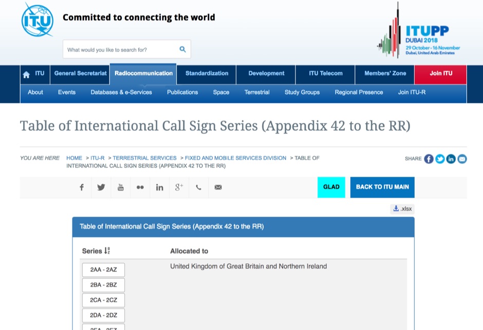 Appendix 42 to the Radio Regulations, published by the International Telecommunication Union (ITU), serves as the authoritative global reference for assigning call sign series to countries. This essential resource allows radio operators, including those in the amateur service, to accurately identify the national origin of a station based on its callsign prefix. It is fundamental for DXers, contesters, and anyone involved in international two-way radio communication, ensuring correct country identification for awards like _DXCC_. The table details the specific blocks of call signs allocated to each administration, facilitating the unambiguous determination of a station's geographical location. For instance, prefixes like K, W, N, and AA-AL are assigned to the United States, while G and M series denote the United Kingdom. Understanding these allocations is crucial for logging contacts and verifying QSLs. This ITU publication is regularly updated to reflect changes in national assignments and new allocations, maintaining its accuracy as the definitive source for call sign series worldwide. It underpins the global framework of radio communication.
 -
 The W6PQL 23cm Beacon Project describes a **1296 MHz** beacon designed for microwave propagation studies and equipment testing, capable of 30 watts output. It utilizes a PIC 16F628A microcontroller to generate CW and FSK keying for a crystal oscillator, followed by a series of frequency doublers and triplers to reach the target frequency. The final power amplification stage employs a Mitsubishi M57762 module, providing a robust 10-watt RF output. The design emphasizes stability and reliability for continuous operation, with the microcontroller code, written in assembly, provided for customization of the beacon's callsign and message. Originally located in CM97am and aimed at 140 true, the beacon used four 4-foot Yagis stacked vertically for a total ERP of 3kW. The article includes schematics, parts lists, and construction notes to guide builders, along with antenna pattern measurements. Although the beacon itself is no longer in service as of August 2010, the detailed documentation remains a valuable reference for amateur radio operators interested in building similar **microwave** projects or understanding beacon operation.