Search results
Query: compact footprint antenna
Links: 26 | Categories: 0
-
 The RXO Unitenna, a vertical wideband antenna, offers operation across the 7-21 MHz spectrum, covering the 40, 30, 20, 17, and 15-meter amateur bands. This design focuses on achieving a low SWR across a broad frequency range, making it suitable for general HF operation without requiring an external antenna tuner for minor SWR variations. The antenna utilizes a unique loading coil and matching network to maintain efficient radiation characteristics across its operational bandwidth. Construction details within the PDF document include specific dimensions for the radiating element and the counterpoise system, which is critical for vertical antenna performance. The design incorporates readily available materials, simplifying the build process for radio amateurs. Performance graphs illustrate the SWR characteristics across the 7 MHz to 21 MHz range, demonstrating the antenna's wideband capabilities. The document also provides guidance on feedline connection and grounding considerations for optimal field deployment. This vertical antenna configuration is particularly useful for hams with limited space, offering a compact footprint compared to horizontal wire antennas.
 -
 The HB9ABX RoomCap antenna document details the construction and performance characteristics of a compact HF antenna design. It presents a series of comparative field tests conducted between July and September 2005, evaluating the HB9ABX antenna against established designs like the Microvert MV-500, Cushcraft R5/R7000 verticals, and a 5-element DJ2UT Yagi beam. Specific test scenarios include mobile installations, rooftop deployments, and comparisons on 20m, 40m, 80m, and 160m bands, with signal reports from various European and DX stations. The resource emphasizes the antenna's small physical footprint and its claimed efficiency across multiple HF bands. Test results consistently show the HB9ABX antenna performing comparably to, and often outperforming, larger reference antennas in terms of received signal strength, with reported differences of 1 to 2 S-points (6-12 dB) in many contacts. Notably, a 20m DX test on July 26, 2005, indicated the 1.3m HB9ABX radiator yielded 2-3 S-points stronger signals than an R7000 vertical for US DX stations. An August 12, 2005, test on 40m highlighted the HB9ABX's superior signal-to-noise ratio in urban QRM, demonstrating 10-18 dB better performance than an R7000. The document includes specific callsigns, signal reports, and QTHs for each comparison, providing empirical data for the antenna's performance claims.
 -
 Optimizing antenna portability for QRP field operations often involves trade-offs between efficiency and physical footprint. The PAC-12 antenna project addresses this by presenting a **multi-band portable vertical** design, specifically tailored for amateur radio operators who travel frequently and utilize compact QRP transceivers like the Elecraft K1/K2 or Yaesu FT-817. This design emphasizes ease of homebrewing using readily available hardware store components, allowing for customizability and repair in the field. The project details the construction of a sectional aluminum rod base, interchangeable loading coils for various HF bands, and a telescoping whip. Key components include 1/4-inch aluminum rod, PVC risers for coil forms, and a BNC feedpoint insulator. The design prioritizes a breakdown length of 12 inches or less, making it highly packable for travel, while still achieving competitive efficiency, as demonstrated by its first-place finish in the HFPack antenna shootout at Pacificon 2001 against a 1/4-wavelength wire vertical. Comprehensive instructions cover whip preparation, **loading coil construction** with specific dimensions for bands from 40m to 10m (with an untested 80m approximation), base section fabrication, and feedpoint insulator assembly. The resource also includes guidance on radial deployment, threading aluminum rod, and showcases various PAC-12 builds by NJQRP Club members, illustrating its adaptability and widespread adoption among QRP enthusiasts.
 -
 For amateur radio operators seeking a compact, directional antenna for the 10-meter band, this resource details the construction of a Moxon Yagi beam. The design utilizes readily available PVC pipe for the boom and elements, with specific measurements derived from the Moxon Rectangle Generator software. It outlines the assembly process for the main boom and end sections, providing critical dimensions for element spacing and overall length to achieve resonance at 28 MHz. The Moxon configuration offers a smaller footprint compared to a traditional Yagi, making it suitable for limited space installations. The article provides practical guidance for hams interested in a DIY antenna project, emphasizing the use of common hardware store materials. It specifies a 1 1/4" PVC schedule 40 pipe for the main boom and details the use of tees, reducing bushings, and 45-degree elbows for the element ends. Key measurements like the 55" spacing for the ends and the 150 3/4" overall length are provided, enabling replication of the design. The Moxon's inherent wide beamwidth and good front-to-back ratio make it an effective choice for DXing on 10 meters.
 -
 Designing a compact directional antenna for the 70cm band involves balancing gain, front-to-back ratio, and physical size. This resource details the construction of a 2-element Moxon rectangle antenna for 432 MHz, outlining the specific dimensions for the driven element and reflector, and discussing the advantages of its folded dipole configuration. The article provides insights into the historical context of 70cm operations and the author's personal experiences with early 432 MHz transceivers and antenna setups, such as a Jaybeam 48-element TV antenna. It also touches upon the practical aspects of building and deploying such an antenna for local and weak-signal work. The Moxon antenna design is compared to a 3-element Yagi, noting its superior front-to-back ratio and broader bandwidth for a given boom length, making it suitable for portable operations or restricted spaces. The construction uses readily available materials like copper wire and PVC tubing, emphasizing simplicity and ease of replication. Performance characteristics, including a reported gain of approximately 5.5 dBi and a front-to-back ratio of 20 dB, are discussed in the context of its compact footprint. The resource includes a visual representation of the antenna's dimensions and construction, aiding in practical implementation.
 -
 Operating on the 12-meter and 17-meter WARC bands often benefits from directional antennas that offer gain and front-to-back ratio in a compact footprint. This resource details the construction of a dual-band wire beam, specifically a _Moxon Rectangle_ design, for these two bands. It outlines the use of fiberglass tubing for spreaders, _Flexweave_ wire for the elements, and an aluminum hub with die-cast flanges to create a robust structure. The design allows for a single 50-ohm feed point, simplifying station setup and minimizing feedline loss. The project provides specific dimensions and material choices, enabling a homebrewer to replicate the antenna. While inspired by L.B. Cebik's (W4RNL) theoretical work, this implementation focuses on practical construction techniques for a physical build. The resulting antenna offers directional characteristics suitable for DXing and contesting on 12m and 17m, providing an alternative to full-sized Yagis or compromise verticals, particularly for those with limited space.
 -
 In 1999, W5GVE presented a detailed construction article for a 2-meter _DDRR_ antenna, specifically designed for mobile operation. This unique antenna, a Directional Discontinuity Ring Radiator, offers a compact footprint, making it suitable for vehicular mounting where traditional quarter-wave verticals might be impractical. The design emphasizes ease of homebrewing, utilizing readily available materials and basic workshop tools, allowing radio amateurs to build an effective mobile antenna for the 144 MHz band. The article provides insights into the antenna's performance characteristics, noting its low profile and potential for reduced wind loading compared to taller mobile whips. W5GVE's experience with the DDRR design suggests it can provide reliable communications on the 2-meter band, even in challenging mobile environments. The construction details include specific dimensions and assembly steps, guiding the builder through the process of creating a functional antenna. This project offers a practical alternative for hams seeking a discreet yet effective 2-meter mobile antenna, potentially achieving **3 dB** gain over a standard mobile whip.
 -
 Illustrates the construction of a compact _Moxon_ beam antenna specifically tailored for the 40-meter band (7 MHz). The resource details a homebrew project by W7XA, emphasizing its design for limited space while maintaining good bandwidth and directivity characteristics. It highlights the practical application of the _Moxon_ rectangle model to achieve performance on a lower HF band. The primary content is a downloadable PDF document titled "40-Meter-Mini-MOXON-Beam-Antenna.pdf," which provides comprehensive illustrations and technical specifications for replicating the antenna. This includes dimensions, materials, and assembly instructions, making it a practical guide for radio amateurs interested in directional antennas for HF. The project demonstrates how a relatively small footprint can yield a directional antenna suitable for DXing or contesting on 40 meters, a band typically requiring much larger arrays for similar gain and front-to-back ratios. The documentation supports hands-on construction.
 -
 A 20-meter Moxon antenna design provides a compact directional solution for the 14 MHz band, achieving approximately **5.5 dBi** of forward gain and a front-to-back ratio exceeding 20 dB. This rectangular wire array, consisting of a driven element and a reflector, offers a smaller footprint than a traditional 2-element Yagi, making it suitable for space-constrained installations. Construction details focus on specific dimensions for the wire elements, fed with 50-ohm coaxial cable. The _Moxon rectangle_ inherently delivers wide bandwidth and a clean radiation pattern, simplifying tuning with a relatively low SWR across the entire 20-meter band. Its robust performance makes it a practical choice for both fixed stations with limited tower space and portable _DXing_ operations. The design's characteristics are particularly beneficial for contesting and long-haul communications on 20 meters.
 -
 Constructing a high-gain, compact antenna for 2 meters often involves balancing theoretical performance with practical build challenges. WB8AHT recounts his journey in building a 6-element _Super Duper Moxon_ antenna for 144 MHz, inspired by designs from M0PXS and GW3YDX. He initially encountered discrepancies in published dimensions for the _HAARP Antenna_ and the _Super Moxon_, leading to on-air SWR issues and suboptimal performance. His methodical approach involved cross-referencing, direct communication with Phil Simpson (M0PXS), and iterative adjustments to element lengths based on observed results and a _SARK-110 Antenna Analyzer_ scan. After modifying the reflector/driven element and third director dimensions, the antenna achieved a respectable 1.35:1 SWR at 144.200 MHz. Field testing with 50 watts yielded contacts up to 500 miles, suggesting performance close to the 15 dBi gain predicted by _4NEC2_ software, despite its compact 40-inch boom. The article includes specific construction notes, such as tubing sizes (1/2-inch and 3/8-inch aluminum) and feedpoint spacing (50mm). The author's experience highlights the importance of real-world validation for antenna designs, even those with strong theoretical backing. He provides a table of tubing lengths for 6m, 4m, and 2m versions, along with his final, optimized dimensions, offering a practical blueprint for fellow hams interested in replicating or further experimenting with this high-performance, small-footprint VHF antenna.
 -
 Constructing an effective mobile antenna system for HF bands often presents challenges in achieving multi-band operation with a compact footprint. This project details the assembly of a versatile mobile antenna utilizing a standard _Hamstick_ base, enabling operation across 40, 20, 15, and 10 meters. The design incorporates a 102-inch whip and a custom-fabricated coil, allowing for quick band changes by adjusting the coil tap point. The document provides a parts list, step-by-step assembly instructions, and tuning considerations for optimizing SWR on each band. It emphasizes practical construction techniques for the coil and mounting hardware, ensuring mechanical integrity for mobile use. The antenna's performance is discussed in the context of typical mobile operating environments, highlighting its adaptability for various HF frequencies. Final adjustments involve precise trimming of the whip and coil taps to achieve resonance, with a focus on minimizing losses and maximizing radiation efficiency.
 -
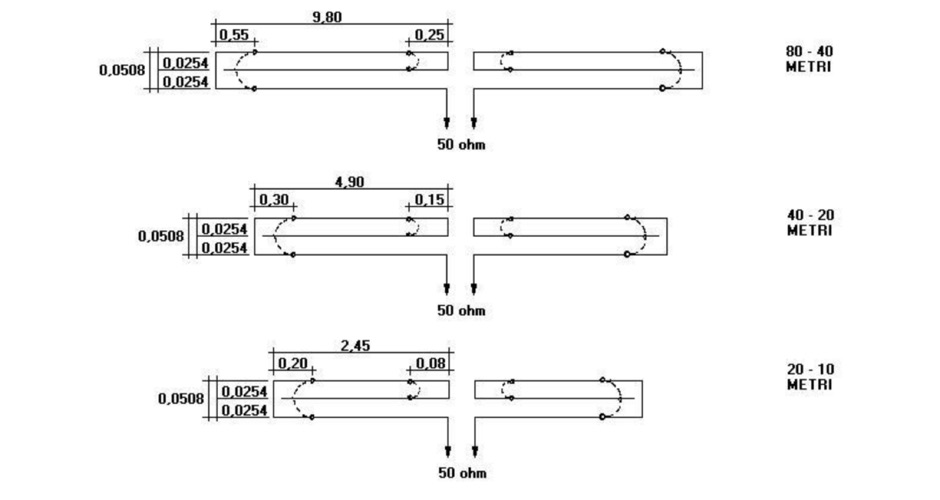 The resource details the historical development of the Morgain antenna, tracing its origins to Virginia in the 1960s and its subsequent global adoption among radio amateurs. It describes the Morgain as a dual-band wire antenna known for its reduced footprint and modest gain characteristics. The content includes discussions on various homebrew projects and design variations available online, providing context for its continued relevance in amateur radio. The article presents a historical overview rather than specific construction plans, focusing on the antenna's evolution and general design principles. It highlights the antenna's enduring appeal due to its performance attributes and compact size, making it suitable for various operating environments.
 -
 The X80 multi-band HF vertical antenna, a commercial iteration of the Rybakov design, exhibits a physical length of 5.5 meters, or approximately 18 feet, and is constructed from aluminum tubing. It operates as a non-resonant vertical, requiring an external antenna tuner for impedance matching across its intended operating frequencies. The antenna's design incorporates a 1:4 UNUN at its base, facilitating a nominal 50-ohm feed point impedance for the coaxial cable. Performance observations indicate effective operation on 40 meters, 20 meters, 15 meters, and 10 meters, with reduced efficiency on 80 meters and 160 meters due to its relatively short electrical length for these lower bands. Comparative analysis with a G5RV dipole and a half-wave end-fed antenna reveals the X80 offers a lower take-off angle, beneficial for DX contacts, particularly on the higher HF bands. Field tests conducted with an Icom IC-706MKIIG transceiver and an LDG AT-100ProII autotuner demonstrate the X80's ability to achieve acceptable SWR across 80m through 10m. The antenna's compact footprint and ease of deployment make it suitable for restricted spaces or portable operations, though its performance on 80 meters is noted as a compromise compared to full-size resonant antennas.
 -
 Presents construction details for Moxon antennas, specifically focusing on 10-meter and 17-meter band configurations. It covers practical aspects of building these directional wire arrays, including element spacing, feedpoint considerations, and material choices for optimal performance. The resource emphasizes homebrewing techniques suitable for amateur radio operators. Discusses the advantages of the Moxon rectangle design, such as its compact footprint compared to a full-size Yagi and its favorable front-to-back ratio. It provides insights into achieving proper impedance matching and structural integrity for portable or fixed installations. The content includes photographic examples of constructed antennas. Explains the iterative process of tuning and optimizing Moxon antennas for specific frequency segments within the 10m and 17m bands. It offers guidance on minimizing SWR and maximizing gain, drawing from real-world building experiences to assist constructors in replicating successful designs.
 -
 Constructing an effective directional antenna for the 40-meter band presents unique challenges due to its physical size requirements. This resource details the homebrew construction of a 2-element _Moxon_ Yagi antenna specifically designed for 7 MHz operation. The author, TA7OM, provides a visual guide to building this antenna, showcasing the boom, element mounting, and feedpoint connections through a series of high-resolution photographs. While textual descriptions are minimal, the imagery clearly illustrates the mechanical aspects of the antenna's assembly. The _Moxon_ rectangle design offers a compact footprint compared to a full-size Yagi, making it a practical choice for many hams with limited real estate. The visual documentation allows builders to replicate the antenna's structure, including the use of PVC pipe for element support and the method for spacing the driven and reflector elements. The project emphasizes practical construction techniques for achieving a directional pattern on a challenging HF band, suitable for DXing and contesting.
 -
 Constructing a compact directional antenna for the 17-meter band, this resource details the build process for a Moxon rectangle, a two-element Yagi variant with folded-back elements. It covers the antenna's evolution from the _VK2ABQ beam_ and provides specific dimensions for a version built using fishing pole whips. The content includes a discussion of the antenna's radiation pattern, feedpoint impedance, and its inherent front-to-back ratio, which is often superior to a standard two-element Yagi. Practical considerations for element spacing and material choices are also addressed, alongside a visual representation of the antenna's physical layout. Performance data presented includes a comparison showing the Moxon rectangle's **2.5 dB gain** over a half-wave dipole and a front-to-back ratio of **20 dB**. The resource also touches upon the antenna's relatively wide bandwidth for a two-element beam and its suitability for portable operations due to its compact footprint. It offers insights into optimizing the design for specific operating conditions and discusses the advantages of its lower take-off angle compared to omnidirectional wire antennas, making it effective for DX contacts on the 17-meter band.
 -
 A 102-inch vertical whip, commonly a CB antenna, forms the core of this low-profile 10-meter antenna design, optimized for the 28 MHz band. The construction details specify three 8-foot radials made from scrap wire, connected to a common point. This simple yet effective setup is designed for ease of construction and deployment, making it accessible for operators with limited space or materials. The design emphasizes using readily available components, including PVC pipe for the mast and a SO-239 connector for the feedline, ensuring a straightforward build process for a resonant quarter-wave vertical. Field results indicate that this antenna provides good performance for local and DX contacts on 10 meters, despite its compact footprint. The author, N8WRL, shares practical insights into its construction and tuning, highlighting its suitability for temporary or permanent installations where a full-sized antenna might be impractical. Comparisons to more complex designs suggest that this low-profile vertical offers a respectable signal-to-noise ratio and effective radiated power for its size, proving that simple designs can yield satisfying on-air results.
 -
 The resource examines the operational characteristics and potential of Moxon Yagi antennas, drawing insights from Les Moxon's work and subsequent NEC modeling. It presents simulated current distributions and radiation patterns for a 40-meter Moxon, comparing its performance against a standard 2-element Yagi on the same band. Specific data points include forward gain, front-to-back (F/B) ratio, and feedpoint impedance, which are critical parameters for antenna design and optimization. Further analysis extends to a 20-meter Moxon, detailing its gain, F/B ratio, and SWR bandwidth across the band. The discussion highlights the Moxon's compact footprint and its ability to achieve respectable performance metrics, making it a viable option for hams with limited space. The content provides a technical assessment of the Moxon's advantages in terms of pattern purity and impedance stability compared to other compact directional arrays. The article also touches upon the practical considerations for constructing and deploying Moxon antennas, emphasizing the trade-offs between physical size and electrical performance. It includes graphical representations of antenna currents and radiation patterns, offering visual aids to understand the theoretical concepts discussed.
 -
 The Tri-pole antenna, a clever modification of a standard dipole, allows for dual-band operation by integrating a third element. This design effectively shortens the overall dipole length by 10 to 20 percent, simplifying antenna rotation and offering a compact footprint. KK4OBI's article delves into the operational principles, using a 6 and 10-meter Tri-pole as a primary example, and provides comprehensive instructions for constructing any Tri-pole antenna within the 6 to 15-meter range. Key to the Tri-pole's performance is its off-center feed, necessitating a common mode choke at the feed point for optimal tuning and reduced noise. The author outlines a methodical approach to determining element dimensions, starting with a vertical element frequency calculated as 0.47 times the sum of the desired upper and lower band frequencies. This calculation, along with K-values derived from trend lines, guides the initial lengths for the horizontal arms, demonstrating how a 10m-6m Tri-pole can achieve a total horizontal length 78% shorter than a conventional 10-meter dipole. Tuning and balancing are critical, with the article detailing adjustments to arm lengths and the vertical element to achieve balanced SWR values, as validated through 4NEC2 simulations. Radiation patterns are analyzed at various elevations, showing gains around 5.7 dBi and favorable take-off angles for DX contacts. Construction details specify aluminum tubing dimensions, U-bolts, and an SO-239 connector, emphasizing the importance of a ferrite-based choke for wideband operation.
 -
 Constructing a directional antenna for VHF operations, particularly for 2-meter band contests or local communication, often involves balancing performance with ease of build. The Moxon rectangle, a compact two-element beam, offers a good front-to-back ratio and gain in a smaller footprint compared to a Yagi, making it suitable for portable or temporary setups where space is limited. This design typically uses a driven element and a single reflector, bent into a rectangular shape to achieve its unique radiation pattern. The article details the construction of a 2-meter Moxon antenna, specifically for 144 MHz, utilizing readily available materials like PVC pipe for the frame and copper wire for the elements. It outlines the dimensions for the driven element at 970mm and the reflector at 910mm, with a spacing of 140mm between them, and a 50mm gap at the element ends. The feedpoint is a direct 50-ohm connection, simplifying matching requirements. The project includes a parts list, a basic diagram illustrating the element layout and dimensions, and photographs of the completed antenna. The author notes the antenna's performance during a QRP contest, achieving contacts up to 100km with 5 watts, demonstrating its effectiveness for low-power VHF work.
 -
 Presents the construction and performance characteristics of the _Moxon Rectangle_ antenna, a compact, directional HF antenna design. It details the antenna's physical structure, emphasizing its robust build and ease of erection compared to traditional Yagis. The resource provides specific dimensions for building Moxons for the 10m through 40m bands, derived from _W4RNL_'s work, and discusses the critical element spacing for optimal performance. It also covers feeding the antenna with a simple choke balun and achieving a low SWR across the band. Compares the Moxon's performance to a two-element Yagi, noting its superior wind resistance and compact footprint. The author, _VK3BCY_, shares personal experiences with a 20m Moxon, reporting SWRs below 1.3 across the entire band and strong signal reports from DX stations with only 100 Watts. EZNEC Pro modeling data is included to illustrate gain and front-to-back ratios, confirming the antenna's high-performance claims. The article also briefly explores multi-band possibilities and reversible configurations.
 -
 A coaxial cable trap is a fundamental component in multiband antenna design, enabling a single radiator to resonate efficiently on multiple frequencies by electrically shortening or lengthening the antenna element. This project focuses on constructing such a trap for a vertical antenna operating on the 10 MHz (30m) and 14 MHz (20m) amateur bands, providing practical insights into its fabrication and integration. The article outlines the specific dimensions and winding techniques for the coaxial trap, emphasizing the use of readily available materials. It details the physical construction of the vertical element, including the mast and radiating sections, to achieve optimal performance across both target bands. The author shares personal experiences with similar trap designs, noting their effectiveness in previous horizontal dipole configurations. Key construction steps are illustrated with _original photos_, showing the assembly of the trap and its incorporation into the overall antenna structure. The design aims for a compact footprint, making it suitable for limited space installations while still delivering effective DX capabilities on the **30-meter** and **20-meter** bands.
 -
 Showcasing German engineering, ANjo Antennen develops and manufactures a diverse portfolio of amateur radio and commercial antenna products. Their offerings span a wide frequency range from 1.8 MHz to 3000 MHz, emphasizing electrical and mechanical precision for longevity. The company actively participates in events like FUNK.TAG Kassel, providing opportunities for direct engagement and order pickup. ANjo's product line includes high-performance **Yagi antennas** optimized for Tropo and EME, along with multi-stacked Quad antennas designed for contest operations, featuring wide horizontal and narrow vertical beamwidths. They also produce circularly polarized satellite antennas, some with switchable LHCP/RHCP, leveraging their commercial satellite antenna expertise. Beyond amateur applications, ANjo provides flexible, custom antenna solutions for commercial sectors such as BOS, EMC measurements, and telemetry. Their commitment to quality is evident in the Premium-Line antennas, which utilize **1.4301 (V2A) stainless steel** for mast clamps and connectors, ensuring durability and corrosion resistance. They also offer end-fed HF multiband wire antennas, known for their compact footprint and discreet installation.
 -
 Illustrates the construction of a mini ununtenna, focusing on practical design elements and component specifications for amateur radio operators. The guide covers the winding of the unun transformer, selection of appropriate ferrite core material, and integration of the radiating element. It specifies wire gauges, core dimensions, and connection points, providing a clear pathway for replication by hams. Compares the ununtenna's performance characteristics against other common wire antennas, highlighting its compact footprint and broadband capabilities. It discusses impedance matching considerations and offers insights into optimizing the antenna for various HF bands, making it suitable for portable operations or limited space installations.
 -
 This article presents a novel Top Loaded End-Fed Half-Wave (TLEFHW) antenna design for 20-meter ham radio operation. The antenna features a compact 14-foot vertical radiator with a capacitance hat configuration, eliminating the need for radials or ground systems. Using EZNEC modeling and field testing, the design achieves a 1.5:1 SWR across the 20m band with a 4.11 dBi gain. Key features include quick deployment, lightweight construction, and directional radiation pattern with 110-degree beamwidth. The design, while requiring a 45-foot footprint due to the top hat, offers an effective portable solution for amateur radio operators seeking a no-ground, no-tuner 20m antenna option.
 -
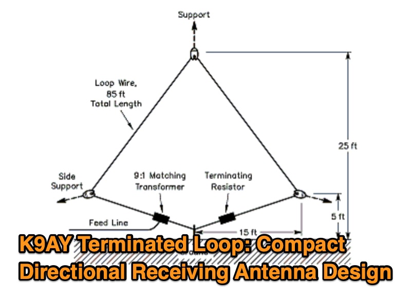 This resource presents the design and characteristics of the K9AY Terminated Loop, a compact directional receiving antenna system. The document details the antenna's physical and electrical configuration, consisting of a wire loop, a 9:1 impedance-matching transformer, and a terminating resistor. It describes how the antenna achieves directionality, favoring signals from the feed point end and rejecting signals from the terminating resistor end by several S units. The system is designed for low-band operation, specifically mentioning its application for improving reception on bands where space is a constraint. A four-direction system, utilizing two loops oriented at right angles with a relay-controlled switching system, is discussed. The resource includes a comparison of the K9AY loop's footprint to that of an equivalent EWE array, indicating the K9AY system requires approximately 1/7 the area while maintaining similar directional patterns. The design prioritizes signal collection sufficient for use with modest preamps, such as those integrated into HF transceivers. The article was originally published in QST in 1997.