Search results
Query: high gain omni
Links: 7 | Categories: 0
-
 This drawing shows a simple 10 meter wire J-pole antenna designed for 28.4 MHz. It is a vertical, end-fed Zepp-style antenna made from common materials and intended for easy home construction. The main radiating element is a straight length of stranded copper wire, either 14 or 18 gauge, cut to about 16.5 feet. At the top, the wire is supported by an insulator, allowing the antenna to be hoisted vertically. The matching section is made from 450-ohm ladder line, approximately 7 feet 9.5 inches long, and shorted at the bottom. This matching stub transforms the impedance so the antenna can be fed with coaxial cable. The feed point is tapped about 6 inches above the bottom of the stub, with the shield and center conductor connected at the proper points. A choke balun is formed with five turns of RG-58 coax in a 4-inch diameter loop to help reduce unwanted RF on the feed line. The drawing notes that this antenna has about 0 dBd gain, similar to a dipole, but offers an omnidirectional pattern and low-angle radiation when installed high. Its main advantage is practical performance, simple construction, and effective coverage for 10 meter operation.
 -
 Selecting an appropriate antenna system for shortwave broadcasting involves evaluating various types based on performance, cost, and operational parameters. This resource details the critical specifications for broadcast antennas, including average and peak power ratings, directivity, takeoff angle (TOA), horizontal beamwidth, and gain, emphasizing that a 100-kW transmitter requires an antenna rated for 150 kW average and 400 kW peak. It clarifies that low TOA signals travel thousands of kilometers, while high TOA is for local coverage, and nearly all modern shortwave broadcast antennas are horizontally polarized. The article explores specific antenna types, such as Log-Periodic Antennas (LPAs), which offer wide frequency ranges (e.g., 2-30 MHz) and directional patterns with 11 dBi gain, costing from $20K to over $100K for multi-curtain versions. Dipole arrays, also known as curtain antennas, are prevalent in international broadcasting, featuring steerable beams (±15° and ±30°) and mode-switching capabilities to alter TOA, with high/low pairs costing over $1 million. Fan dipoles are noted for omnidirectional patterns, smaller size, and lower cost for low-power applications, while rhombics, though simple, require resistive termination and incur several dB of I2R losses. Balun considerations are crucial, as most communications baluns are not rated for the higher average and peak powers of AM broadcast transmitters. Modern shortwave antennas utilize durable materials like Alumoweld wire rope for radiators and support elements, avoiding copper, fiberglass, or materials prone to stretching or deterioration. Feeder systems for high-power stations often require tapered-line baluns to convert 50-ohm unbalanced power to 300-ohm balanced for connection to the antenna.
 -
 802.11b WLAN Waveguide Antennas Unidirectional & Omnidirectional. High gain, Simple construction by Trevor Marshall
 -
 Autotena, a Taiwanese manufacturer, offers a diverse product line focused on RF communication antennas and related accessories. The resource details various antenna types, including **4G/3G LTE wideband high-gain low-profile antennas**, land mobile wideband antennas, fiberglass omnidirectional designs, and GPS mobile and marine antennas. Specific amateur radio offerings include NMO VHF load coil gain antennas, VHF whip gain antennas with PL-259 connectors, and UHF NMO mount antennas with 3dB/5dB gain. The company also produces antennas for CB and 10-meter amateur bands, such as aluminum broadband 26-30MHz antennas and big copper coil broadband 26-30MHz antennas. Additionally, the site showcases **RF amplifiers** for CB, HF, VHF, and UHF bands, including professional-grade base station amplifiers with 100% EIA duty cycle. Handheld antennas, PL-259 type mobile antennas, magnet mount antennas, and external CB speakers are also presented, alongside various mounting kits and cable assemblies.
 -
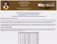
 Operating an 80/40/20M fan dipole for DX is analyzed through EZNEC modeling, focusing on the antenna's performance in a real-world, low-height installation. The resource details the physical construction and SWR measurements of the fan dipole, comparing them against EZNEC simulations. It also incorporates High Frequency Terrain Analysis (HFTA) data to illustrate typical DX elevation angles for various regions from New England, providing a crucial context for evaluating antenna patterns. The analysis presents EZNEC-generated azimuth and elevation patterns for each band (80M, 40M, 20M) at specific frequencies, showing gain figures at different elevation angles relevant to DX propagation. It compares the modeled SWR with measured SWR, attributing discrepancies to coax attenuation. The study concludes with observations on the antenna's azimuth performance (omnidirectional within ±1.5 dB) and its less optimal elevation gain at desired DX angles, highlighting the impact of low antenna height on DX capabilities.
 -
 The collinear antenna, or Marconi-Franklin antenna, is an omnidirectional, high-gain antenna composed of in-phase half-wave dipoles aligned vertically. By using quarter-wave transmission line segments, it maximizes gain at a low horizon angle, outperforming a half-wave dipole. Adding segments increases gain but narrows bandwidth. A popular DIY version, the CoCo antenna, uses half-wave coaxial cable segments connected by non-radiating transmission lines. Built with stable velocity factor cables, a matching quarter-wave sleeve balun, and ferrite rings for attenuation, the antenna achieves performance comparable to commercial models.
 -
 Operating amateur radio satellites presents unique challenges, particularly concerning antenna design and signal propagation. Juan Antonio Fernández Montaña, EA4CYQ, recounts his three-year journey into satellite communication, starting with initial guidance from EB4DKA. His early experiments involved a portable 1/4 wave VHF antenna with four 1/4 wave ground planes, designed for hand-held use to adjust polarity. This setup, paired with an FT-3000M transceiver, allowed full-duplex operation on **VHF** transmit and **UHF** receive, proving effective for early contacts on satellites like AO27, UO14, and SO35. EA4CYQ's experience highlights the critical role of coaxial cable loss and antenna polarization. After encountering significant signal degradation with longer RG213 runs, he experimented with a 1/2 inch commercial cable, noting improved reception but persistent fading due to varying satellite polarities. This led to the construction of an **Eggbeater II** antenna, an omnidirectional UHF design offering horizontal polarization at the horizon and circular right polarization at higher elevation angles. Subsequent modifications resulted in the directional **TPM2** antenna, which provided sufficient gain for LEO satellites with a wide 30-degree lobe, enabling consistent contacts from his home station. The article concludes with practical insights on the performance of the Eggbeater II for both UHF and VHF, and the TPM2 for UHF, emphasizing their utility for portable and fixed operations. EA4CYQ's journey underscores the iterative process of antenna development and the importance of adapting designs to overcome real-world propagation challenges in satellite communications.