Search results
Query: isotropic radiator
Links: 6 | Categories: 0
-
 Examines the rationale behind L. B. Cebik, W4RNL's, consistent use of dBi for specifying antenna gain in his modeling work, contrasting it with the common practice of using dBd. The article meticulously defines decibels as relative power measurements and introduces the theoretical _isotropic radiator_ as the baseline for dBi, highlighting its utility as an unchanging constant for universal antenna comparison. It details how maximum gain in dBi allows for straightforward numerical comparisons between antennas, while also emphasizing the importance of considering other factors like horizontal beamwidth, vertical beamwidth, and elevation angle of maximum radiation for a complete performance picture. The resource then critically analyzes the concept of dBd, categorizing it into _dBd-I_ (ideal dipole), _dBd-RM_ (real modeled dipole), and _dBd-RR_ (real range dipole), exposing the ambiguities and inconsistencies inherent in these varied definitions. W4RNL argues that the lack of standardized protocols for dBd measurements, particularly in real-world test ranges, makes direct comparisons problematic without extensive supplementary data on test conditions and comparison antennas. He illustrates how these complexities often obscure rather than clarify antenna performance. Ultimately, the article advocates for dBi as the more robust and unambiguous standard for antenna modelers, especially when comparing diverse antenna types where a dipole is not a relevant benchmark. It acknowledges that range testers may continue to use dBd-RR due to practical limitations, but stresses the critical need for detailed test protocols to ensure meaningful results. The discussion underscores the ongoing challenge of correlating real-world antenna measurements with theoretical modeling.
-
 The QM7 antenna is a simple 7 elements Yagi with 3.70 m boom length for the lower 144 MHz SSB/MGM band, used it mainly for Sporadic-E and MS contacts. It exhibits a forward gain of 11.35 dBd; i.e. 13.5 dB forward gain over the isotropic radiator, while the F/R is about 12.5 dB
-
 One common challenge for radio amateurs involves interpreting antenna gain specifications, which are often presented using various units like dBi or dBd. This article clarifies the distinctions between isotropic, dipole, and effective radiated power (ERP) gain measurements, providing a foundational understanding for selecting appropriate antennas. It details how dBi references an isotropic radiator, dBd compares to a half-wave dipole, and ERP integrates transmitter power with antenna gain. Understanding these gain metrics is crucial for accurately assessing an antenna's directional characteristics and overall efficiency in a specific operating environment. The resource explains how to convert between dBi and dBd, noting that 0 dBd equals 2.15 dBi. It also touches upon the practical implications of these values in real-world antenna performance, helping operators make informed decisions about their station's radiating system.
-
 The decibel (dB) is a logarithmic unit used to measure sound level, widely applied in electronics, signals, and communication to describe power, sound pressure, voltage, or intensity ratios. For instance, a 3 dB increase signifies a doubling of power, while a 10 dB increase represents a tenfold power multiplication. Sound pressure level is calculated as 20 log (p2/p1) dB, reflecting the square relationship between power and pressure. Standard reference levels, such as 20 micropascals for sound pressure in air, establish absolute dB values, where 0 dB corresponds to the reference level, not an absence of sound. Human hearing sensitivity varies with frequency, necessitating A and C weighting filters (dBA, dBC) in sound meters to approximate the ear's response. The phon unit relates to dB via psychophysically measured frequency response, with 1 kHz readings being identical. The sone unit quantifies perceived loudness, where 1 sone equals 40 phons, and a 10 dB increase above 40 phons roughly doubles perceived loudness. In radio, dBi measures antenna gain relative to an isotropic radiator, crucial for anisotropic radiation patterns.
-
 Antenna directivity and gain are fundamental concepts for any radio operator, as this article from _Electronics Notes_ explains. Real-world antenna designs, unlike theoretical isotropic radiators, do not radiate equally in all directions; their radiation patterns are often visualized using **polar diagrams**. These diagrams illustrate how power is focused in desired directions, crucial for both transmitting and receiving applications. The article clarifies how antenna performance is identical for both transmission and reception, a key principle for understanding antenna specifications. Operators often encounter terms like _beamwidth_, which defines the angle where power falls to half its maximum level, or -3dB. Understanding this parameter is vital for accurately orienting directional antennas like a Yagi. The discussion also differentiates between antenna gain expressed in dBd (decibels over a dipole) and dBi (decibels over an isotropic source), noting that dBi figures will always be **2.1 dB** higher than dBd. This distinction is critical when comparing antenna specifications to ensure an accurate assessment of performance. Furthermore, the article touches on the front-to-back ratio, another important metric for directional antennas, and the balance between maximizing forward gain and achieving an optimal front-to-back ratio.
-
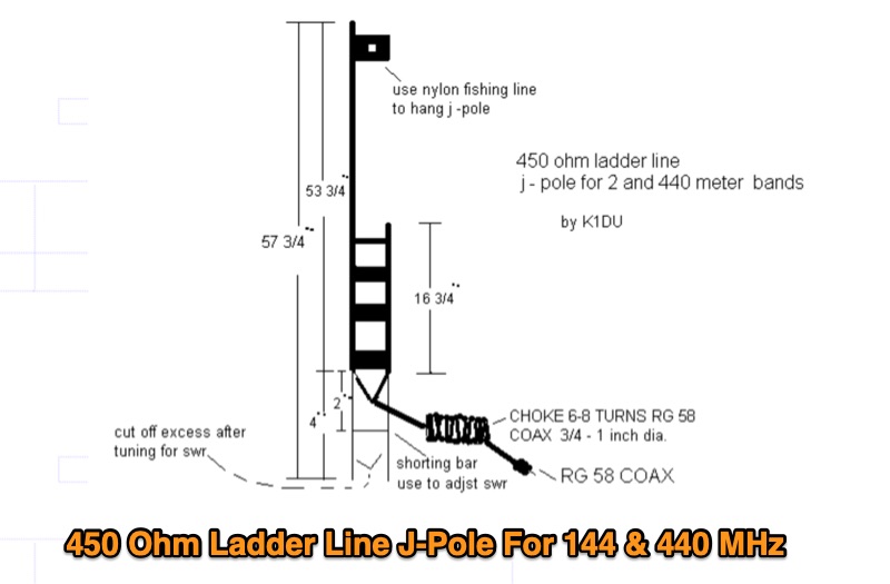 Constructing a **J-Pole antenna** from 450 Ohm ladder line for 2-meter (144 MHz) and 70-centimeter (440 MHz) operation involves specific calculations and assembly steps. The design, based on an earlier KD6GLF concept using 300 Ohm twinlead, features a ¾ wavelength radiator and a ¼ wavelength matching stub, functioning as an end-fed half-wave antenna without requiring ground radials. It offers a gain of 2.4 dB over isotropic. The resource provides the formulas for determining the lengths of the ¾ wave radiator and ¼ wave stub, incorporating a velocity factor of 91% for 450 Ohm ladder line. For 146 MHz, the radiator measures 55 3/16 inches and the stub 18 3/8 inches. Construction details include cutting a 57¾-inch piece of ladder line, stripping 4 inches from one end, and attaching a 24-inch section of RG58 or RG8X coax with a 3-5 turn RF choke. SWR adjustment is achieved by sliding a shorting bar or by incrementally trimming the elements at a 1:3 ratio (stub to radiator). The goal is a 1:1.1 SWR at 146 MHz, which typically yields 1:1.2 at 446 MHz. The article also discusses power handling, noting that while 10-15 watts is fine, 50 watts may increase SWR to 1:2.1, and advises keeping the antenna away from other objects to prevent coupling and SWR degradation.