Search results
Query: lindenblad antenna
Links: 12 | Categories: 2
Categories
-
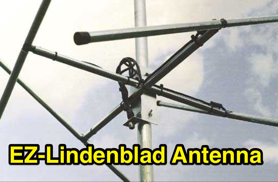 This easy to build antenna works well for satellite or terrestrial communication, horizontal or vertically polarized by Anthony Monteiro, AA2TX QST Article
 -
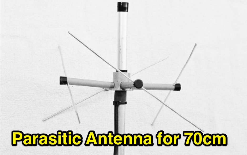 A Parasitic Lindenblad Antenna for 70cm by Anthony Monteiro, AA2TX. This is the official 16 pages PDF File published by AMSAT about the 70cm Parasitic Lindenblad Antenna.
 -
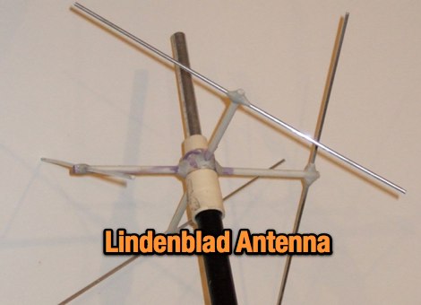
 The ultimate satellite Omni Antenna by Howard Sodja, W6SHP. The Lindenblad antenna consists of four half wave folded dipoles slanted 30 degrees to the horizon, oriented 90 degrees to each other in azimuth, spaced 0.3 wavelength apart
 -
 Constructing a Lindenblad antenna for 137MHz NOAA satellite reception involves specific design considerations for optimal performance. The resource details the use of 4mm galvanised steel fencing wire, 300-ohm television ribbon cable, and wood/plastic components for the antenna structure. Key dimensions for a 137.58MHz-resonant antenna are provided, derived from the ARRL Satellite Handbook, specifying s, l, w, and d as 42, 926, 893, and 654mm respectively. The antenna is designed for Right Hand Circularly Polarised (RHCP) signals, requiring the four folded dipole elements to be tilted clockwise by 30 degrees. A significant aspect covered is impedance matching between the antenna's 75-ohm impedance and a typical 50-ohm receiver input. A twelfth-wave matching transformer, constructed from 117mm sections of 50-ohm RG-58 and 75-ohm RG-59 coax with a 0.66 velocity factor, is described. The article also addresses coaxial cable and connector selection, recommending 75-ohm Type-N connectors for RG-6 cable in professional setups and F56/F59 connectors for general use, while strongly advising against PL-259/SO-259 connectors for VHF. Strategies for mitigating Radio Frequency Interference (RFI) are discussed, including antenna placement to shield from local TV transmitters and the use of commercial or DIY band-pass filters, such as cavity resonators or helical notch filters, along with ferrite chokes on coaxial cables. Antenna orientation is explored, noting the Lindenblad's 'cone of silence' directly overhead and its maximized sensitivity towards the horizon. An experimental vertical tilt of 90 degrees is presented as a method to improve overhead reception and reduce interference from strong horizontal signals, particularly relevant in high RFI environments like the Siding Spring Observatory site.
 -
 The antenna is a vertical dipole, around which four parasitic elements are forming a circle.
 -
 A Lindenblad Antenna for 145 MHz and 435 MHz with an integrated 50 MHz J-pole
 -
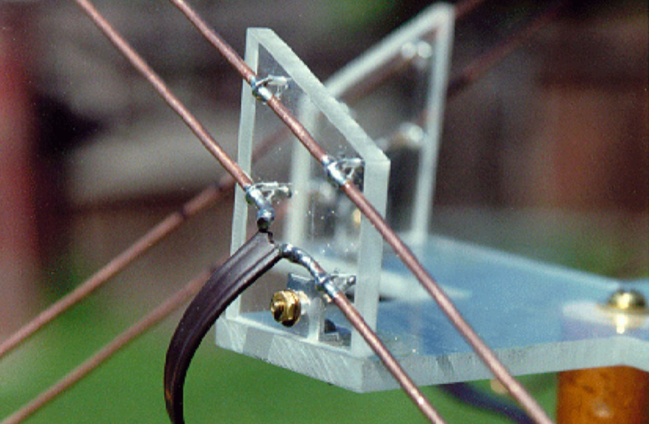
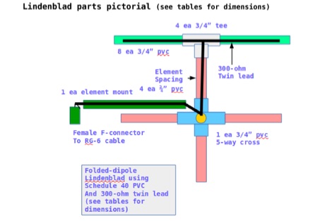 This document contains the detailed instructions to build a homemade lindenblad antenna using a twin-lead as dipole elements. This document contains 9 pages and includes a detailed construction sequence and some drawings to build this antenna for UHF and VHF ham radio bands
 -
 3d parts printed to build an EZ-Lindenblad 2 Meters LEO Sat antenna as designed from Anthony Monteiro
 -
 An homebrew Lindenblad antenna designed specifically for LEOs reception.
 -
 This is a presentation used at OVARC on the LindenBlad antenna construction. The presentation cover several topics about this antenna, from the basic antenna design, to the guide on how to contruct a custom lindenblad antenna for the 2 meters band and and 70 centimenters band.
 -
 This Antenna project is a bit more complex than other omni antennas for satellite use, but it is much easier and cheaper than a standard tower mounted circular polarized azimuth and elevation rotating beam system.
 -
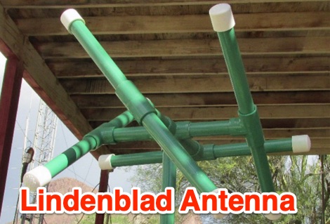
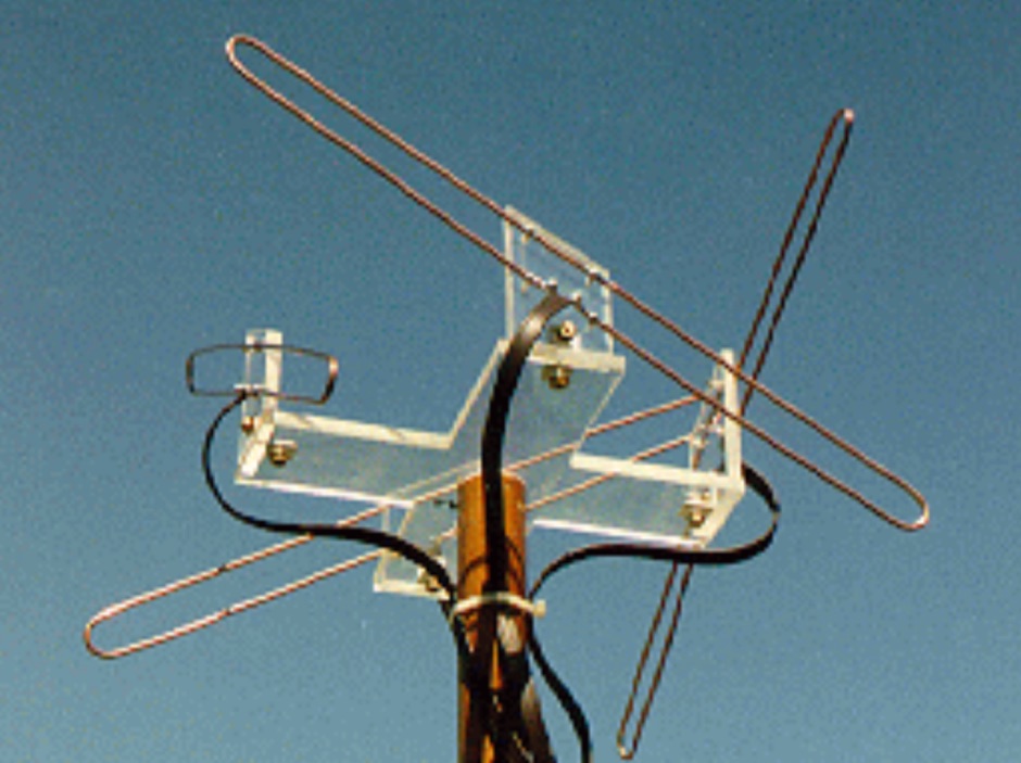
 The article describes the construction of a Lindenblad antenna, which is well-suited for receiving signals from low-orbiting weather satellites. The key points are: The Lindenblad antenna has an omnidirectional horizontal radiation pattern and is optimized for low to medium elevation angles, making it ideal for tracking passing satellites near the horizon. It is designed to receive circular polarization, which is common for weather satellite signals. The antenna is constructed using 4 folded dipole elements arranged on a cross-shaped frame. The necessary materials include a plastic junction box, PVC tubing, and aluminum rods to form the dipole elements. The article provides detailed instructions for preparing the components, assembling the dipoles, and connecting the feed lines to create the complete antenna. The completed antenna can be mounted on a vertical support, with the dipole elements angled at 30 degrees from horizontal, to optimize reception of the passing satellites. The author notes that the design was originally published in a now-defunct magazine, Meteo Satellite Inf", in 1993