Search results
Query: lowe electronics
Links: 4 | Categories: 0
-
 The UK amateur radio licensing scheme features three distinct tiers: Foundation, Intermediate, and Full, each granting specific operating privileges. For instance, the **Foundation Licence** permits a maximum of 10 watts output power on most allocated bands, with restricted band access. The Intermediate Licence allows up to 50 watts, while the **Full Licence** grants access to the maximum UK legal power limits and all available amateur radio band allocations. UK call sign prefixes and formats provide insights into the licensee's class and the approximate issuance date. For example, M3, M6, and M7 prefixes with three letters denote Foundation Licences issued from 2002, 2008, and 2018 respectively. Intermediate Licences, often starting with "2E0" or "2E1" followed by three letters, were issued from 1991 onwards. Full Licences encompass a broader range of prefixes like G2, G3, G4, G0, and M0, with varying letter counts indicating different historical license classes and issuance periods, such as G3 plus three letters issued between 1946 and 1971. Special prefixes like GB are reserved for repeaters, beacons, data mailboxes, and special event stations, with specific numerical sequences (e.g., GB3 for repeaters, GB7 for data repeaters/mailboxes) indicating their function. Optional prefixes such as GC, GD, GI, GM, and GW denote specific UK countries (e.g., Wales, Isle of Man, Northern Ireland, Scotland, England) and can also signify club stations.
 -
 UK dealer for pmr audio accessories, batteries and cases, audio accessories and airwave tetra products
 -
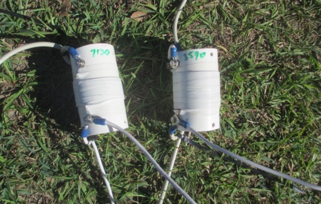 A Trapped dipole inverted V antenna for lower HF Bands. Construction details are for temporary installation. Permanent installations will require additional ruggedising and waterproofing however the basic electronics concepts remain the same. This project includes SWR plots for the three bands and pictures details of the homemade traps.
 -
 Documents the design and construction of a **four-band Moxon beam** antenna, covering 20, 15, 10, and 6 meters. Author W7JMP shares his journey from initial research and computer modeling using 4NEC2 to the final on-air testing and optimization. The project aimed for gain over a dipole on 20 meters, with a budget under $500, including the antenna rotor. The design incorporates fiberglass spreaders and a single feedpoint, avoiding complex relay switching. The article details the selection of materials, assembly techniques, and the critical tuning process. W7JMP describes fabricating the hub, mounting spreaders, and attaching elements made from stripped THTN wire. A notable innovation is the use of a half-wave tuning stub with a loading coil for in-situ adjustment of the 20-meter reflector, optimized via remote S-meter readings using a webcam and smartphone. This method allowed for fine-tuning the **front-to-back ratio** without lowering the antenna. Initial testing revealed a dipole-like pattern, which was significantly improved after tuning, resulting in reported 2 to 4 S-unit front-to-back ratios and enhanced signal strength for DX contacts on multiple bands, including sporadic E on 10 and 6 meters.