Search results
Query: peak circuit
Links: 7 | Categories: 0
-
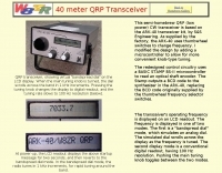 The project details modifications to an ARK-40 QRP CW transceiver kit, specifically replacing its original thumbwheel frequency selectors with a **BASIC STAMP BS-II microcontroller** and an optical shaft encoder. The redesigned control circuitry outputs a BCD code to the ARK-40's synthesizer, enabling more convenient knob-type tuning. This modification significantly alters the user interface, moving from discrete frequency selection to continuous tuning. Operating frequency is presented on an LCD readout, offering two distinct display modes: a "bandspread dial" mode that simulates an analog dial scrolling across the display in 1 kHz increments, and a conventional digital readout with 100 Hz resolution. Pushing the main tuning knob toggles between these modes, providing both rapid band traversal and fine-tuning capabilities. The software for the BASIC Stamp is written in P-Basic, addressing the challenge of accurate analog dial simulation. Physical modifications include fabricating a custom PC Board for the STAMP, mounting it with an L-bracket to the optical encoder, and creating a new front panel. The front-mounted speaker was relocated to accommodate the new tuning knob and display, transforming the **ARK-40 transceiver** into a more user-friendly rig with its built-in CW keyer and 5 watts of power.
-
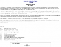 Demonstrates building a basic _VOX circuit_ to add voice-operated transmit functionality to HF transceivers that lack this feature. The design utilizes a _1458 dual op-amp_ (two 741 op-amps in one package) to amplify microphone audio and act as a comparator, driving an NPN switching transistor for PTT control. A capacitor, C2, provides the necessary delay before unkeying the PTT, with a variable resistor, R6, allowing adjustment of the VOX level for specific microphones or voices. This low-cost circuit, detailed with a full parts list, offers a practical solution for hams seeking to enhance their budget HF rigs. The author, N1HFX, provides guidance on initial setup, including advice on microphone gain and the use of headphones to prevent speaker audio from re-keying the transceiver. Modifications for adjusting delay time are also included, suggesting increasing R8 to 10K for more delay or decreasing C2 to 22µF for less.
-
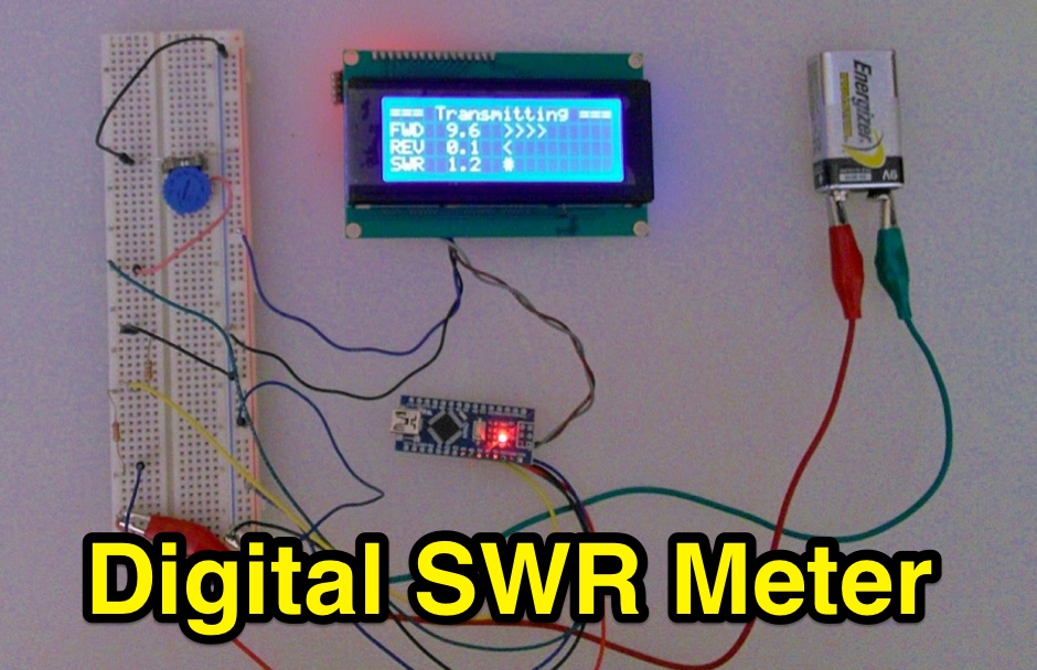 Inline RF Power & VSWR Meter. A DIY meter 0 to 30 Watt with Average and Peak. Circuit Description, Arduino Nano software code and part list to DIY your own Digital SWR Meter
-
 Protecting amateur radio equipment from transient overvoltages requires robust lightning and surge protection, which is the focus of Electronic Specialty Products. The company provides various devices, including coaxial lightning arrestors for antenna feedlines and surge protectors for AC power lines and data circuits. These devices are engineered to divert high-energy surges, such as those caused by direct or indirect lightning strikes, away from sensitive transceivers, amplifiers, and computer components, thereby preventing catastrophic damage. Key products include the _Coaxial Lightning Protector_ series, designed for various impedance levels and frequency ranges up to 3 GHz, and the _AC Line Surge Protector_ for shack power distribution. Effective deployment of these protection devices can significantly reduce the risk of equipment failure and ensure operational continuity during severe weather. For instance, a properly installed coaxial arrestor can handle peak currents of **20 kA**, while AC line protectors offer clamping voltages typically below 400V. Comparing different models reveals varying levels of insertion loss and return loss, with some coaxial units exhibiting less than 0.1 dB loss at 500 MHz, making them suitable for high-performance HF and VHF/UHF operations. Integrating these components into a comprehensive grounding system is crucial for achieving maximum protection against both common-mode and differential-mode surges.
-
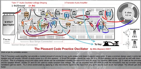 The Twin-T code practice oscillator project provides an amplified, shaped sine-wave output, ideal for Morse code training. This circuit design utilizes a 3-transistor audio amplifier, ensuring a clear and robust audio signal for practice sessions. The oscillator's core is a Twin-T RC network, which is critical for generating the sine wave at an audible frequency. Construction details include component values and a schematic diagram, guiding builders through the assembly process. The design focuses on simplicity and effectiveness, making it accessible for those new to electronics while still offering a high-quality audio output. The amplified signal allows for use with headphones or a small speaker, enhancing the learning experience for CW operators.
-
 Operating in a Single Operator Two Radios (SO2R) setup, especially with beverage antennas, often exposes the receiving radio's front-end to significant RF energy from the transmitting radio. This resource details a practical, homebrew receiver protection circuit designed to mitigate this risk. The core of the design involves a non-inductive 2W 22 Ohm carbon composition resistor in series with the RX antenna line, followed by two stacks of four fast-switching diodes (e.g., _1N914_) configured in opposite polarizations. This arrangement effectively clamps the incoming voltage to approximately 2.8 V peak-to-peak, safeguarding sensitive receiver input components. The series resistor plays a crucial role by absorbing excess power, preventing the diodes from exceeding their current ratings and potentially failing open, which would leave the receiver unprotected. The author, _N4KG_, measured up to 50 watts of coupled power between 80M slopers on the same tower, highlighting the necessity of such protection. The design is presented as a cost-effective solution to prevent damage to receiver input transformers, with the author noting successful protection of a receiver even after a resistor showed signs of overheating. This simple circuit can be integrated via a transverter plug, offering a robust defense against high RF input.
-
 The Yaesu FTDX10 is presented as a compact HF/50MHz 100W SDR transceiver, employing a Hybrid SDR configuration that integrates Narrow Band SDR and Direct Sampling SDR. The Narrow Band SDR receiver features a Down Conversion design with a 9MHz first IF, incorporating 500Hz, 3kHz, and 12kHz crystal roofing filters. This architecture achieves a Reciprocal Mixing Dynamic Range (RMDR) of 116dB or more, a Blocking Dynamic Range (BDR) of 141dB or more, and a 3rd Order Intermodulation Dynamic Range (3rd IMDR) of 109dB or more in the 14MHz band at 2kHz separation. The local oscillator circuit utilizes a 250MHz High Resolution Direct Digital Synthesizer (HRDDS) method, contributing to a phase noise characteristic of -145dB or less in 14MHz at 2kHz separation. The transceiver incorporates a 5-inch Full-Color TFT display with touch-panel functionality, featuring a 3DSS (3-Dimensional Spectrum Stream) display for enhanced visualization. Front panel controls include an MPVD (Multi-Purpose VFO Outer Dial) for operational efficiency. Remote operation capabilities are supported with the optional SCU-LAN10 unit. Additional features include 15 separate band pass filters, IF DSP for QRM rejection, a high-quality final amplifier with RD70HUP2 MOSFETs, an aluminum heat sink with an 80mm cooling fan, and a high-speed automatic antenna tuner with 100-channel memory. The page also lists various accessories such as the SP-30 external speaker, XF-130CN 300Hz roofing filter, and several microphone models, alongside links to product brochures, operating manuals, and firmware updates.