Search results
Query: pll control
Links: 4 | Categories: 0
-
 PA3FWM's software defined radio (SDR) page documents his extensive hardware and software development efforts between 2004 and 2009. Initial experiments utilized a direct conversion receiver with 90-degree phase difference, feeding a PC soundcard at 48 kHz sample rate, covering 24 kHz of spectrum around a 7080.5 kHz local oscillator. This setup, similar to AC50G's QEX 2002 article, allowed for basic I/Q signal processing to distinguish signals above and below the LO frequency. Limitations included fixed crystal frequencies, 16-bit dynamic range, and narrow bandwidth. Subsequent hardware iterations aimed for enhanced performance, incorporating external 24-bit ADCs with 192 kHz sample rates, connected via 10 Mbit/s Ethernet. A **MC145170-based PLL** and programmable octave divider provided a 58 kHz to 30 MHz tuning range. The **Tayloe mixer** was employed, with differential outputs feeding a PCM1804 ADC. An ATmega32 microcontroller handled serial data conversion to Ethernet frames, though without CRC calculation due to processing constraints. Later designs integrated AD7760 2.5 Msamples/second ADCs and a Xilinx Spartan-3 FPGA, enabling direct reception of 0-1 MHz spectrum and eventually 2.5 MHz bandwidth across the shortwave spectrum. Software was refactored to use an initial 8192 non-windowed FFT for efficient high-bandwidth processing. The project culminated in a two-way QSO on 21 MHz using the developed hardware and software, demonstrating transmit capabilities with a D/A converter. The system exhibited a 2.5 MHz wide spectrum display and a zoomed 19 kHz display, capturing signals like ionospheric chirp sounders and RTTY contest activity. Challenges included noise leakage from digital circuitry and cooling for high-power dissipation components.
 -
 A synthesized 2.3 GHz Amateur Television (ATV) transmitter design, conceived by Ian G6TVJ, is presented, targeting broadcast-quality video performance on the 13cm band and extending up to 2.6 GHz. The core of the design utilizes a commercial Z-comm Voltage Controlled Oscillator (VCO) that tunes from 2.2-2.7 GHz, providing a +10 dBm output and simplifying RF alignment. This VCO's stability, originally intended for narrowband applications, readily accepts high-frequency video modulation, contributing to the transmitter's robust performance. The exciter stage, incorporating a Mini Circuits VNA 25 MMIC amplifier, boosts the signal to +16dBm, while a Plessey SP4982 prescaler divides the output frequency for the synthesizer. The synthesizer employs a Motorola MC145151 CMOS parallel IC, favored over the common Plessey SP5060 for its superior video modulation characteristics and ease of programming without microprocessors. This choice addresses issues like LF tilt and distorted field syncs often seen with SP5060 designs, particularly when operating through repeaters or over long distances. The MC145151 divides the signal further, enabling precise frequency stepping, with programming handled by EPROMs for channel selection and LED display. The loop filter network, critical for video integrity, was developed through experimentation to prevent the PLL from reacting to video modulation, ensuring a clean transmitted picture. The transmitter incorporates a Down East Microwave commercial power amplifier module, delivering approximately 1.6W output, driven by the exciter through a 3dB attenuator. Construction involves surface-mount SHF components on micro-strip lines etched onto double-sided fiberglass board, housed within a tinplate box. The design boasts no AC coupling in the video path, preserving low-frequency response, a common failing in other ATV transmitters. Performance tests with a 50Hz square wave revealed no LF distortion, and a calibrated "Pulse & Bar" signal showed a near 100% HF response, demonstrating its capability for high-quality ATV transmissions.
 -
 Constructing a high-performance RF spectrum analyzer up to 1000 MHz requires careful attention to component selection, shielding, and circuit isolation. This resource details a project that improves upon the _Spectrum Analyzer for the Radio Amateur_ design by Wes Hayward (W7ZOI) and Terry White (K7TAU), incorporating ideas from Scotty Sprowls' project, particularly his 1013.3 MHz IF bandpass cavity filter. The analyzer utilizes a Mini-Circuits SRA-11 mixer with a sweeping local oscillator from 1013 to 2013 MHz, feeding into a 4-pole copper pipe cavity filter. The design employs a second SRA-11 mixer with a fixed 1024 MHz LO to produce a 10.7 MHz final IF. This signal then passes through narrowband resolution filters and is processed by Analog Devices AD603 and AD8307 ICs for IF amplification and logarithmic detection, driving an oscilloscope in X/Y mode. The project emphasizes modular construction, using salvaged components and double-sided FR4 material for PCBs, with critical notes on minimizing spurious images through effective shielding and proper voltage regulation for each module. Key components include a Z-Communications V585ME48 VCO for the first LO and a Z-Comm V583ME01 VCO controlled by a Motorola MC145151 PLL for the second LO. An optional Hittite HMC307 step attenuator and K&L 5L121-1000/T5000-O/O low-pass filter manage RF input. Tuning procedures for the 10.7 MHz IF resolution filter are also detailed, showing before-and-after spectrum views.
 -
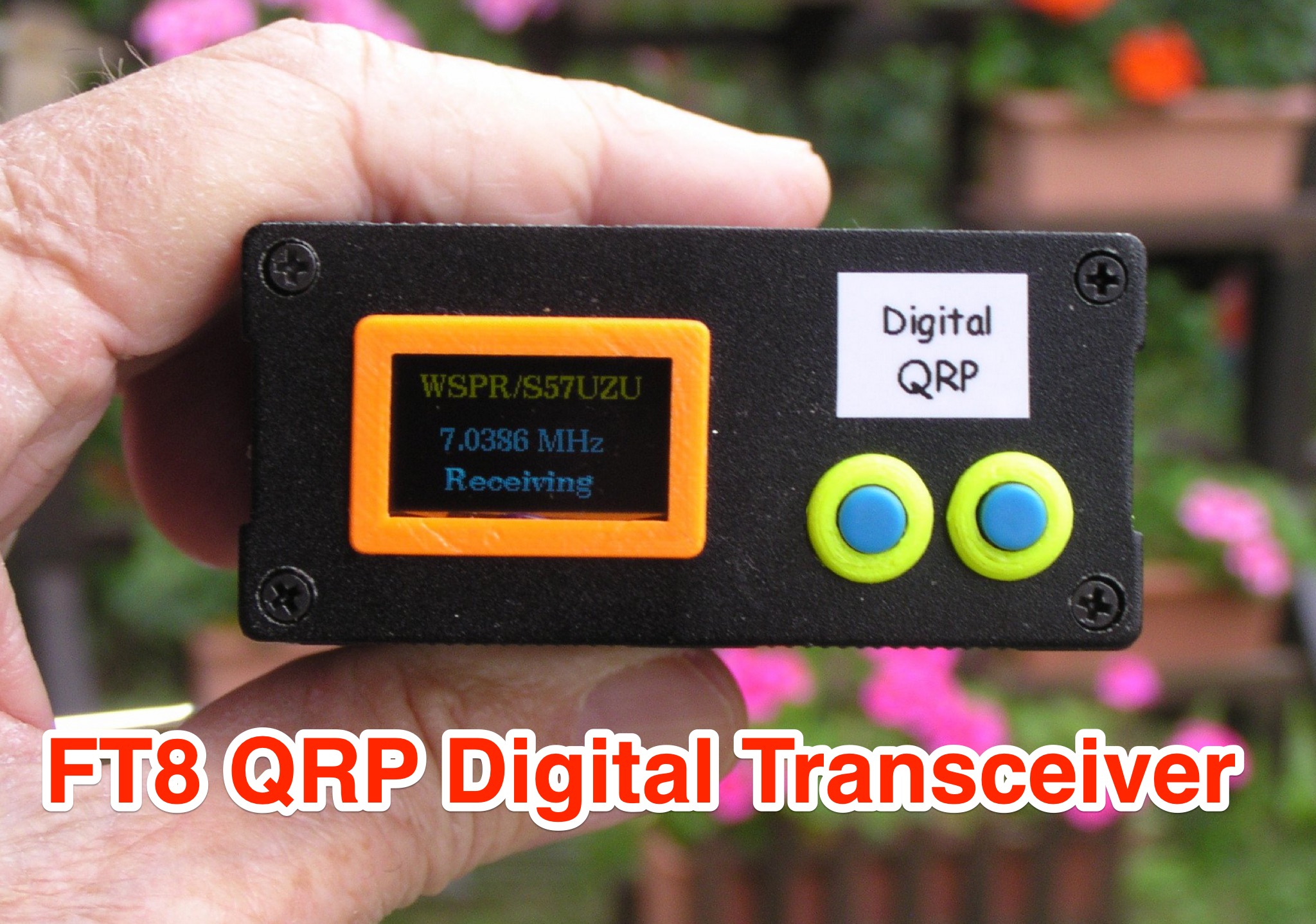 Learn how to build a QRP digital transceiver with Arduino, based on a project by Burkhard Kainka. This article covers the development process, including the source code, modifications made, and the addition of an OLED display for a more professional look. Discover the inner workings of the transceiver, from the receiver to the oscillator, and how components like the CD2003 are utilized. Explore the schematic design, the use of a PLL module Si5351A controlled by Arduino nano, and more. Ideal for hams looking to create their own digital transceiver for amateur radio operations.