Search results
Query: solid state hf amp
Links: 15 | Categories: 2
-
 Presents _Henry Radio Inc._ as a manufacturer of solid-state RF power amplifiers, detailing their capabilities across HF, VHF, and UHF bands. The company designs and builds custom amplifiers tailored for various applications, including amateur radio, commercial broadcasting, military, scientific, and industrial uses. These amplifiers are manufactured in the USA, emphasizing domestic production. Beyond amplifier manufacturing, the resource highlights Henry Radio's role as a distributor for _Bird RF Test Equipment_, including wattmeters, dummy loads, and attenuators. It also mentions _Tohtsu Coaxial Relays_ and a range of miscellaneous amplifier parts and electronic accessories, providing a broader scope of communication equipment offerings. Additionally, the site describes a trunking two-way radio system operating on the 450-476 MHz band, covering significant portions of Los Angeles and Orange County. This service caters to professional dispatch needs for ambulances, taxis, and other commercial entities, requiring no long-term contracts.
 -
 A solid state amplifier for HF and 6 meters band by N4IP
 -
 This is a project to develop an Open Source reference design for a 1500 watt solid state linear amplifier for 10 through 160 meters by K6IF
 -
 Thierry LOMBRY, ON4SKY, develops in three long articles all you need to know about amplification, and how to seletc an HF and a solid-state amplifier, with pictures.
 -
 Constructing a high-power solid-state amplifier for HF operations presents unique challenges, particularly when aiming for significant output like 600 watts. This project details an amplifier design employing **Motorola MRF150** FETs, a common choice for their robust performance in RF power applications. The design emphasizes achieving substantial power output, a critical factor for effective DXing and contesting, where every decibel can make a difference in signal propagation and readability. While specific circuit diagrams or construction details are not directly presented on the current page, the mention of MRF150 FETs points towards a design that would typically involve push-pull configurations, impedance matching networks, and robust power supply considerations to handle the high current demands. Such amplifiers are often built with an eye towards linearity and efficiency across the HF bands. Amateurs pursuing similar high-power solid-state projects often share insights on thermal management, intermodulation distortion, and component sourcing, all vital for a stable and reliable amplifier capable of delivering 600 watts into a proper antenna system.
 -
 This resource details the computer-optimized design of the _ZS6BKW_ multiband dipole, an evolution of the classic _G5RV_ antenna. It begins by referencing the original 1958 RSGB Bulletin article by Louis Varney G5RV, explaining the operational principles of the G5RV's flat-top and open-wire feedline on 20m and 40m, noting its impedance transformation characteristics for valve amplifiers of that era. The article then transitions to the rationale for optimizing the design for contemporary solid-state transceivers requiring a 50 Ohm match. The core of the project involves using computer modeling to determine optimal lengths for the flat-top and matching section, aiming for a VSWR of less than 2:1 on multiple HF bands. It discusses the process of calculating feedpoint impedance based on antenna length and frequency, referencing professional literature from Professor R.W.P. King at Harvard University. The analysis also considers the characteristic impedance (Z(O)) of the open-wire line, identifying a broad peak of adequate values between 275 and 400 Ohms. Specific design parameters for the improved ZS6BKW are presented, including a shorter flat-top and a longer matching section compared to the original G5RV, with a velocity factor of 0.85 for the 300 Ohm tape. The article confirms acceptable matches on 7, 14, 18, 24, and 28 MHz bands when erected horizontally at 13m, and also discusses performance in an inverted-V configuration, noting frequency shifts. The author, Brian Austin ZS6BKW, emphasizes the antenna's suitability for modern 50 Ohm coaxial cable without a balun.
 -
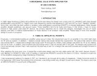
 A Solid State HF Amplifier with 16 mrf150 featuring 2.4 kW 1.8 MHz - 30 MHz
 -
 What makes a good solid-state amp ? by Adam Farson, VA7OJ/AB4OJ, May 2002
 -
 Constructing a high-power 70cm solid-state amplifier presents unique challenges, particularly when aiming for 500 watts output using modern LDMOS devices. This resource details the author's experience building a 70cm amplifier based on a _Freescale MRFE6VP5600H_ transistor, initially from an RFHAM kit. It meticulously outlines the necessary modifications to achieve advertised performance, including optimizing input and output matching, correcting bias circuitry, and ensuring proper output balun connections for stability. The author shares specific adjustments, such as trimming the prototyping board for better transistor fit, drilling additional mounting holes for improved heat sinking, and replacing original matching capacitors with a single _20pf MIN02 metal mica_ for superior output. A critical fix involved jumpering gate decoupling pads to balance the push-pull transistor halves, which increased output to 580W and improved IMD. The resource also highlights a crucial correction to the output balun connection, initially reversed in the _Dubus_ article schematic, which resolved intermittent stability issues. Test results are provided, showing input power, output power, and drain current at 50V, demonstrating the amplifier's performance after modifications. This practical account offers valuable insights for hams undertaking similar high-power UHF amplifier projects, especially those working with LDMOS devices and kit-based constructions.
 -
 Measuring the output impedance (Zs) of solid-state broadband HF amplifiers operating in class AB eham article by ZS6BIM
 -
 Makers of the worlds smallest automatic solid state HF amplifier Expert 1K-FA, Expert 2K-FA and Expert 1.3K-FA
 -
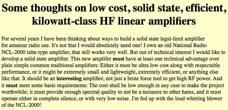 Thoughts build a solid state legal-limit amplifier for amateur radio use.
 -
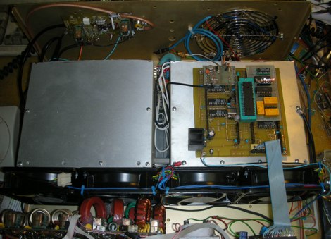
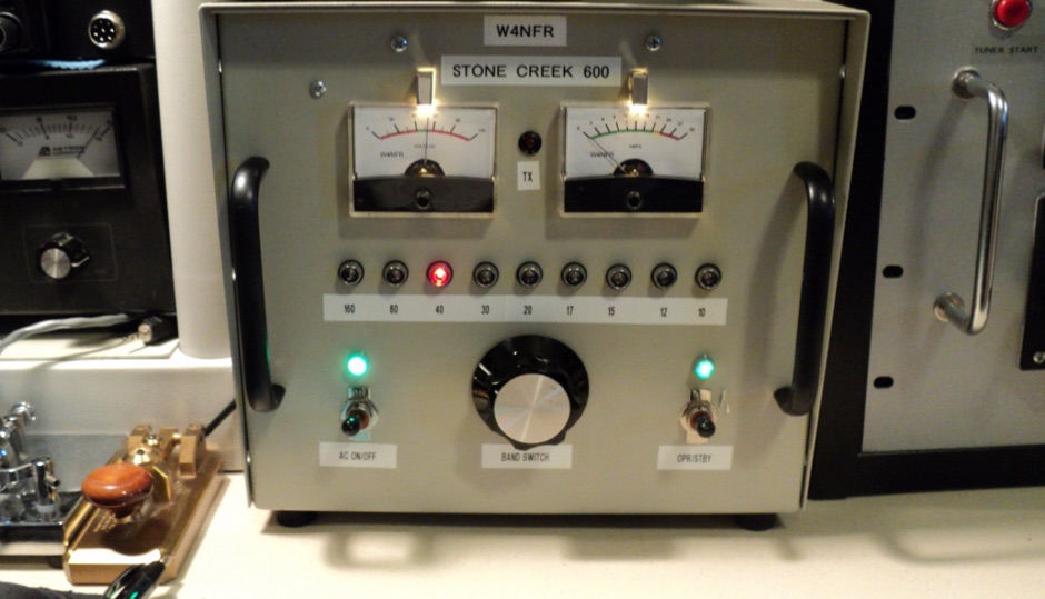 This is a Solid State Amplifier Project. It uses 4 MRF150 MosFet Power Transistors. The Power Supply Voltage is 50 VDC at 21.5 Amp. The max power available is 1,075 Watts. The Efficiency is about 65% +/- and runs Class AB Solid State.
 -
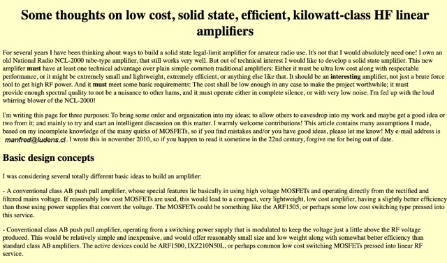 Not a project yet, but very theoretical thoughts about very practical amplifiers!
 -
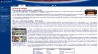
 This document provides a comprehensive guide on purchasing high-frequency (HF) high-power amplifiers, discussing key considerations such as new versus used models, tube versus solid-state technology, and troubleshooting common issues. It emphasizes the importance of understanding power needs for activities like DX chasing and contesting, alongside practical tips for selecting and maintaining amplifiers to ensure reliability and performance in various conditions.