Search results
Query: swr protection
Links: 5 | Categories: 0
-
 Demonstrates the construction and implementation of a **two-element phased vertical array** for 40 meters, utilizing _Christman phasing_ techniques. The author, W4NFR, details the process from building individual 1/4-wave aluminum verticals to integrating them into a phased system. The resource covers antenna spacing of 32 feet, elevated radial design, and the critical steps for tuning each vertical to achieve a 1.1:1 SWR before combining them. It also provides insights into calculating precise coax lengths for feedlines and the phasing delay line, emphasizing the use of an MFJ-269 Antenna Analyzer for verification. The finished system exhibits good front-to-back nulls, with an overall SWR ranging from 1.6:1 to 2.2:1, which is managed by an antenna tuner. The project includes detailed photos of the relay box, showing 12 VDC relays capable of handling 5KV, and the control box in the shack for switching between three different antenna pattern configurations. Static bleed-off chokes are incorporated for protection, and the construction emphasizes robust weatherproofing for outdoor elements.
 -
 This document details the design and construction of the PA70H, a 50-watt RF amplifier for the 70MHz (4-meter) amateur radio band. Built around the Mitsubishi RD70HVF1 MOSFET transistor, the amplifier delivers 45-55W output with 3-5W input power while operating on 13.8V DC at approximately 7-8A. The PCB design incorporates multiple protection circuits including overcurrent, SWR, and temperature control. The amplifier features various control modes including GND PTT, +13.8V PTT, and RF VOX. Two versions are available: PA70HLI (requiring 100mW input with additional driver) and PA70H (for 3-5W input). The comprehensive documentation includes circuit diagrams, assembly instructions, and performance data showing successful operation from both 100mW and 3.5W input sources.
 -
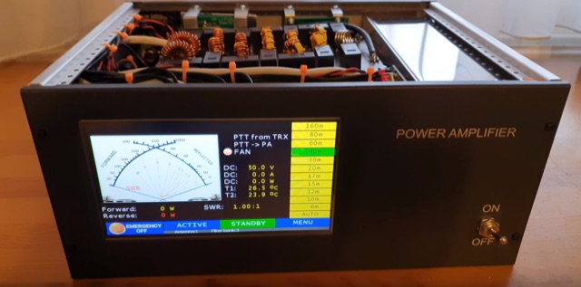 A comeplete home made 600W LDMOS RF power amplifier. Settings can be made on a 7-inch touch screen, and on this screen you can see a lot of useful information during operation, such as output power, temperature, SWR, and so on. The power amplifier includes 2 MRF300 LDMOS FETs and several built-in sensors. The amplifier also contains several types of protection functions like too high current, too high swr, too high temperature, etc.
 -
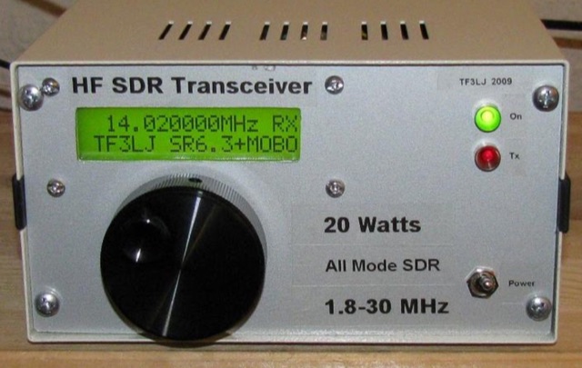 This project describes a DIY all band HF SDR transceiver. Built around a Softrock 6.3 kit, it boasts a 20W homebrew amplifier and ATmega168 microcontroller for USB control. An LCD displays frequency, power, and SWR. Automatic LPF selection and SWR protection enhance functionality. Compatible with Rocky and PowerSDR software, this project provides a cost-effective and powerful HF SDR transceiver for hobbyists.
 -
 Offers a range of high-performance RF interconnect solutions, addressing the critical need for reliable signal integrity across diverse radio frequency applications. Their product line includes custom cable assemblies, various **RF connectors** (such as SMA), adapters, and terminators, designed to meet stringent specifications from DC up to 40 GHz. These components are essential for maintaining low insertion loss and excellent VSWR in demanding environments, from test benches to operational communication systems. The company specializes in providing tailored solutions for both commercial and government sectors, emphasizing precision manufacturing in Warner Robins, Georgia. Their offerings are crucial for engineers and operators requiring specific lengths, connector types, and performance characteristics for their radio equipment and test setups. Ensuring robust connections and protection against transient voltage events, their **surge protectors** are integrated into systems to safeguard sensitive electronics from damage, a common concern in outdoor or high-power installations.