Search results
Query: wire antenna receiving k
Links: 14 | Categories: 0
-
 A quick and easy to build loop antenna for shortwave listeining can tune from 5 to 18 Mhz
 -
 A 2-meter Turnstile antenna, detailed for amateur satellite communication, offers a straightforward build for those looking to engage with orbiting transponders. The author, WB8ERJ, shares his personal design and construction methods, emphasizing the antenna's simplicity and effectiveness for LEO (Low Earth Orbit) satellite work. This design provides a circularly polarized signal, crucial for mitigating _Faraday rotation_ and signal fading often encountered with linearly polarized antennas when tracking satellites. Construction involves readily available materials like PVC pipe and copper wire, making it an accessible project for many hams. The article includes practical advice on element spacing and feed point considerations, drawing from the author's hands-on experience in the shack and field. It highlights the antenna's utility for receiving signals from various amateur satellites, including the popular AO-91 and AO-92. The Turnstile's inherent omnidirectional pattern in the horizontal plane, combined with its circular polarization, yields consistent signal reception, often resulting in **stronger decodes** and **more reliable contacts** compared to basic dipoles or verticals.
 -
 The W1TAG LF Receiving Loop is a specialized antenna project for LF reception, designed to mitigate local noise and enhance weak signal pickup on the lower frequencies. This square loop, measuring 6 feet per side, utilizes 14 turns of #12 THHN wire wound on a PVC frame, offering a robust mechanical structure. The design incorporates a series-tuned circuit with a coupling transformer, allowing for tuning from over 400 kHz down to _45 kHz_ using a switched capacitor bank. Construction details include the use of 1.5-inch PVC pipe for the frame, with specific measurements for spreaders and drilled holes for wire threading. The two 7-turn sections of wire are connected at the center, providing an option for a center tap. The loop rotates on a 1-inch steel pipe, enabling directional nulling of noise sources. The tuning unit, housed in a box clamped to the PVC, employs a 1:2 step-up transformer wound on an _FT-82-77 core_ and uses relays to switch capacitance values from 50 pF to 6400 pF, providing precise frequency adjustment. The current setup connects to the shack via 100 feet of RG-58, feeding into a W1VD-designed preamp, with plans for a balanced, shielded twisted pair cable upgrade.
 -
 The early 20th century saw significant advancements in wireless communication, culminating in the first successful transatlantic radio signal. This historical account details Guglielmo Marconi's pioneering efforts, from his initial experiments with electromagnetic waves to his patented wireless system in 1900. It describes the technical challenges of long-distance radio transmission, particularly the prevailing belief that radio waves would be lost due to the Earth's curvature over vast distances. On December 12, 1901, Marconi established a receiving station in Newfoundland, Canada, utilizing a _coherer_ and balloons to elevate the antenna. Signals, consisting of the Morse code letter "S" (pip-pip-pip), were transmitted from Poldhu, Cornwall, England. The successful reception of these faint but distinct signals across **1,700 miles** confirmed Marconi's theories, marking an epoch in communication history. This achievement demonstrated the viability of global wireless communication, paving the way for future developments in radio technology.
 -
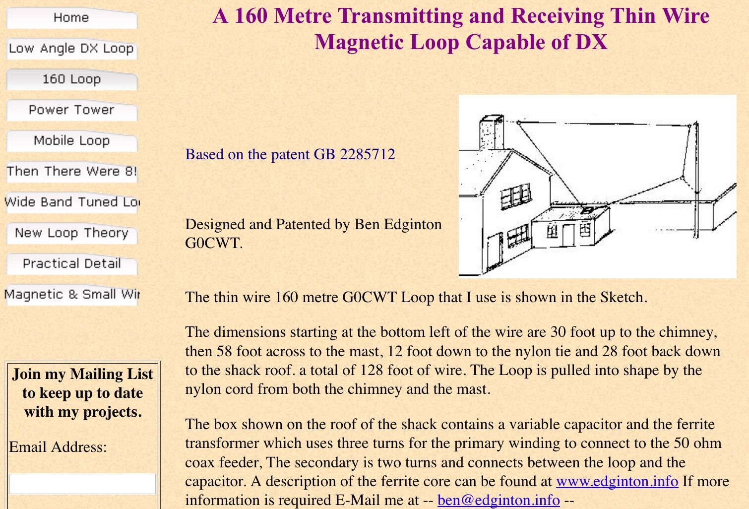 A 160 Metre Transmitting and Receiving Thin Wire Magnetic Loop Capable of DX. Designed and Patented by Ben Edginton G0CWT
 -
 On December 12, 1901, Guglielmo Marconi successfully received the first transatlantic wireless communication, a Morse code "S" (three dots), at 04:30 GMT. This article details the setup for this groundbreaking experiment, noting Marconi's receiver in St. John’s, Newfoundland, Canada, utilized a _coherer_ and an antenna elevated by balloons and kites. The transmitting station at Poldhu, Cornwall, England, featured twenty-four 200-foot ships' masts and a 25-kilowatt alternator. The resource explains how this contact disproved contemporary beliefs about radio wave limitations due to Earth's curvature, later understood through _ionospheric propagation_. It frames Marconi's achievement as the "very first DX" in amateur radio terms, defining DX as telegraphic shorthand for distance and _DXing_ as the hobby of receiving distant signals. The article also provides external links for further reading on Marconi's experiments and the science behind transatlantic radio signal reception.
 -
 This article presents an innovative homebrew antenna design utilizing surplus ladder line as a receiving antenna for HF and MF bands. The Ladder Line Antenna (LLA) transforms standard 450-ohm ladder line into a directional, bidirectional, or omnidirectional antenna system through different termination methods. The design, which requires minimal space and height, achieves 6-10dB front-to-back ratio on 40-160m bands using a 33-foot length. This DIY wire antenna project offers an efficient, low-profile solution for amateur radio operators, featuring broadband operation without ground radials and easy installation below fence height.
 -
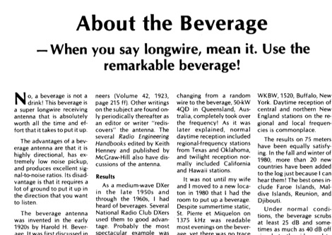 An article about the Beverage antennas, super long wire receiving antennas thar are unidirectional and have a very low noise that makes this antenna excellent for low band dxing. By Thomas R. Sundstrom W2XQ, 73, June 1981, 73 Magazine
 -
 WB8LZR details the construction and initial field results of a multi-band vertical wire antenna, designed to complement his existing horizontal loop for improved DX on 80 meters. The antenna utilizes a 67-foot vertical wire, configured as a quarter-wave radiator on 80m, and employs a 1:1 current balun for RF isolation on 80m, 30m, and 17m. For bands like 40m, 20m, and 10m, where the wire acts as a half-wave or full-wave radiator, an additional impedance transforming _unun_ is integrated to manage the significantly higher feedpoint impedance and voltage. The author notes the vertical's performance as a receiving antenna, observing reduced noise compared to his main horizontal loop, particularly on 80m, and even hearing some long-path signals the loop missed. Initial QRP contacts, including a **1-watt** QSO with a _VP2 station_ on 30m, demonstrate its transmit capability. While the radial system is currently rudimentary, the project outlines practical considerations for multi-band vertical deployment and impedance matching.
 -
 This page provides information about building a Beverage antenna for hams. The article discusses using a 60m wire on the ground to create an effective antenna for amateur radio operators. Learn how to set up and optimize this type of antenna for better reception and communication. This describes a low-noise receiving Beverage antenna setup for low bands, using a N30 cup core transformer for 1:4 impedance matching (likely 50:200 Ohm), RG-58 feedline with heavy common-mode choking, and conduit for wire burial.
 -
 This resource details the construction and performance of a compact broadband magnetic loop antenna designed for portable receiving applications with devices like the _ATS MiniRadio_. The antenna utilizes approximately 3 meters of 0.5–1 mm copper wire wound in two turns on a rhomboidal wooden frame, measuring 50 cm by 70 cm. It connects via a modified 9:1 unun, where the primary center tap is isolated from ground to improve common-mode noise rejection. The design provides untuned operation across a frequency range from the longwave band up to approximately 25 MHz. Performance characteristics include observable directivity for noise suppression and the ability to connect directly to a radio or via a 50 coaxial cable for remote operation. The article specifies the unun's 3:1 turns ratio and its SMA output for connectivity. The methodology focuses on practical construction and observed reception quality.
 -
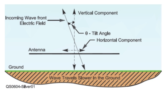 This article explores Beverage antennas, a type used for low-frequency radio reception. Despite the mystique, they are relatively simple wire antennas placed near the ground. Their key benefit is improved signal-to-noise ratio by rejecting unwanted signals. While lengthier antennas offer better reception, even shorter versions (around 200 feet) can improve DX reception compared to traditional antennas.
 -
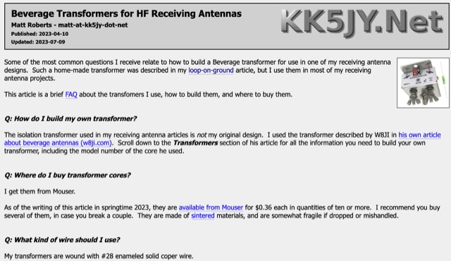 This FAQ covers building and buying transformers for loop-on-ground and Beverage antennas. Building one uses ferrite cores and thin wire. Buying is an option, with the DX Engineering BFS-1 being recommended. These transformers isolate the antenna from the cable to prevent unwanted signal pickup.
 -
 Details the construction and performance of a phase-controlled receiving array, specifically a **MicroSWA** variant, optimized for QRP low band fox hunting on 40M and 80M. The resource documents the author's iterative design process, addressing significant regional noise challenges encountered during 0100-0230 UTC fox hunt periods. Initial experiments involved a director wire on a 40M vertical, yielding limited improvement, prompting a shift towards advanced null-steering techniques. The project leverages concepts from Victor Misek’s "The Beverage Antenna Handbook" and Dallas Lankford’s extensive work on phased receiving antennas for urban lots. A key modification involved integrating a new passive phase control box and a push-pull **Norton common base preamp** using 2N5109 transistors, designed for high third-order intercept performance to maintain weak signal integrity amidst strong adjacent signals. The system incorporates Faraday-shielded transformers with RG174 primaries on -75 ferrite cores, housed in ABS plastic pipe. Performance tests confirmed the MicroSWA's ability to produce deep, steerable nulls, achieving approximately 30 dB noise reduction on 160M, 80M, and 40M. This enabled detection of QRP signals undetectable on conventional transmit antennas. The final unit includes front panel controls, a 10-11 dB preamp, and a robust power conditioner, demonstrating effective noise mitigation for challenging low band QRP operations.