Search results
Query: beam direction
Links: 29 | Categories: 0
-
 For radio amateurs considering homebrew antenna projects, this resource details several designs from WE6W, an experienced operator. It covers the construction and characteristics of a _160 Meter QRP Loop Antenna_ optimized for high voltage, along with standard and folded variations of the double bazooka antenna. The site also presents a unique Field Day antenna design and instructions for building a Sterba Curtain, a directional array known for its gain. Each design includes practical insights from the author's building experience. The author provides comparative data, such as the performance of a standard bazooka against a traditional dipole, offering real-world context for antenna selection. The Sterba Curtain section includes notes on its beamwidth and gain, crucial parameters for directional operation. These designs are suitable for hams looking to experiment with cost-effective, high-performance antennas for various bands and operating scenarios, from QRP on 160m to directional DXing with a Sterba Curtain, which can offer significant forward gain, often exceeding **10 dB**.
 -
 Here you will find information about wire antennas as well as directional beams.
 -
 Selecting an appropriate antenna system for shortwave broadcasting involves evaluating various types based on performance, cost, and operational parameters. This resource details the critical specifications for broadcast antennas, including average and peak power ratings, directivity, takeoff angle (TOA), horizontal beamwidth, and gain, emphasizing that a 100-kW transmitter requires an antenna rated for 150 kW average and 400 kW peak. It clarifies that low TOA signals travel thousands of kilometers, while high TOA is for local coverage, and nearly all modern shortwave broadcast antennas are horizontally polarized. The article explores specific antenna types, such as Log-Periodic Antennas (LPAs), which offer wide frequency ranges (e.g., 2-30 MHz) and directional patterns with 11 dBi gain, costing from $20K to over $100K for multi-curtain versions. Dipole arrays, also known as curtain antennas, are prevalent in international broadcasting, featuring steerable beams (±15° and ±30°) and mode-switching capabilities to alter TOA, with high/low pairs costing over $1 million. Fan dipoles are noted for omnidirectional patterns, smaller size, and lower cost for low-power applications, while rhombics, though simple, require resistive termination and incur several dB of I2R losses. Balun considerations are crucial, as most communications baluns are not rated for the higher average and peak powers of AM broadcast transmitters. Modern shortwave antennas utilize durable materials like Alumoweld wire rope for radiators and support elements, avoiding copper, fiberglass, or materials prone to stretching or deterioration. Feeder systems for high-power stations often require tapered-line baluns to convert 50-ohm unbalanced power to 300-ohm balanced for connection to the antenna.
 -
 The document details the optimization and construction of the _Maria Maluca_ antenna, a compact 6-band (20m-6m) directional beam. It presents a comparative analysis of shortwave antenna principles, highlighting the efficiency gains achieved by using an open feeder line and tuner as a resonant unit, contrasting this with the losses associated with traps or capacitive loads in multiband antennas. The resource specifically revisits an older South American 2-element design for 10, 15, and 20 meters, applying modern NEC-based software to develop a six-band version. Performance data is meticulously tabulated, showing impedance, free space gain, gain at 12m height, elevation angle, and front-to-back (F/B) ratio for each band from 20m through 6m. For instance, on 15m, the antenna achieves 5.1 dBd free space gain and 13.72 dB F/B ratio. The construction section provides practical guidance on element assembly using aluminum pipes and hose clamps, detailing the use of a heavy-duty glass fiber reinforced polyamide rod for electrical separation and bending strength. It also specifies the use of 450-ohm _Wireman_ line CQ 552 for the transmission line. The document includes diagrams for rod fixing, an air-wound balun, and a vertical elevation diagram for the 15m band, illustrating its DX qualification. It also discusses the antenna's suitability for portable and expedition operations, noting its compact transport dimensions (max 1.50m length, 12 lb weight) and quick assembly time (under 15 minutes). The author, Dipl.Ing. Helmut Oeller, DC6NY, is identified as a source for material kits.
 -
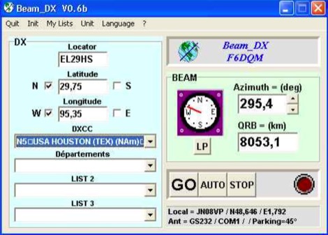 BEAM_DX is a free windows software for radioamateurs or radio listeners usage. It allows to point a directionnal antenna towards an azimuth, a locator, an international prefix or any other geographical position on earth predefined by its latitude and its longitude
 -
 JJ0DRC's HF multi-band delta loop antenna project, initially conceived during the waning peak of Cycle 23, addresses the common challenge of achieving effective DX operation from a small residential lot in Japan. Dissatisfied with a ground plane antenna's performance in SSB pile-ups, the author sought a beam-like solution without a tower, drawing inspiration from a JJ1VKL article in CQ Ham Radio Sep. 2000. The antenna, constructed in October 2000, employs two 7.2-meter fishing rods (37% carbon fiber, reinforced with cyano-acrylate glue and aluminum tape) and 1mm enameled wire, fed by an Icom AH-4 external antenna tuner. While the exact beam pattern remains unmeasured, JJ0DRC observed a significantly higher callback rate compared to dipole antennas, particularly on higher bands. The system's circumference length of 15-20m is crucial for maintaining a good beam pattern across HF bands, though performance on lower bands like 80m, 40m, and 30m becomes less directional as the length deviates from a full wavelength. Ongoing maintenance addressed degradation issues, including aluminum tape cracking and wire breakage at connection points due to strong winds (often exceeding 10-15m/s in winter). The author reinforced rod connections with IRECTOR PIPE SYSTEM components and INSU-ROCK ties, and improved wire attachment methods using Cremona rope and epoxy bond to enhance durability.
 -
 Presents a comprehensive guide for constructing a broadband Hex Beam antenna, a popular directional array for HF operation. This design offers a compact footprint and excellent gain characteristics, making it suitable for limited space installations while providing significant performance advantages over omnidirectional antennas. The resource details the specific dimensions for a five-band Hex Beam covering 20, 17, 15, 12, 10, and 6 meters, emphasizing the critical element spacing and wire lengths required for proper resonance and pattern. It outlines the construction of the center post, spreaders, and wire elements, along with the feed point assembly, ensuring proper impedance matching. The project aims for a forward gain of approximately **5.5 dBi** on most bands, with a front-to-back ratio often exceeding _20 dB_. Building this antenna requires careful measurement and assembly, but the resulting performance provides a substantial upgrade for DXing and contesting.
 -
 The Vee Beam antenna project presents a versatile solution for hams, enabling operation across all eight High Frequency bands (80m to 10m) with significant gain on 20m to 10m. This easy-to-construct antenna utilizes two long wires at an angle, enhancing directional performance and minimizing ground losses. With a low visual profile, it is discreet and effective for various applications. The design allows for optimal leg lengths and included angles, ensuring robust performance while maintaining simplicity in construction and operation. The V Beam antenna is an aerial that you can use on all eight High Frequency amateur bands (80, 40, 30, 20, 17, 15, 12 and 10m) with an antenna tuner, and which gives significant gain on the five bands from 20 to 10 meters band.
 -
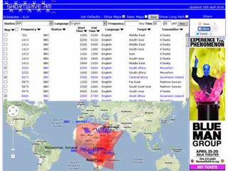 Shortwave Radio Schedules from Eibi/AOKI combined lists. Includes Google maps showing beam directions and long paths.
 -
 50 MHz meteor scatter offers a unique opportunity for amateur radio operators to make long-distance QSOs, even when the band appears dead. Meteor scatter involves reflecting radio waves off the ionized trails left by meteors burning up in the upper atmosphere, typically around 105 km high. These trails can facilitate contacts over distances up to approximately 2,300 km. The technique is particularly effective during meteor showers, which increase the number of meteors and thus the chances of successful QSOs. However, random meteors can also be used to achieve contacts, especially on the 50 MHz band, where the longer reflection time compared to 144 MHz makes it easier to work meteor scatter. Operators should be prepared to make QSOs in short bursts, often lasting only a few seconds. The IARU Region 1 meteor scatter procedure recommends using 2.5-minute periods for telegraphy and 1-minute periods for SSB, though shorter periods can be arranged. For 50 MHz SSB, 15-second timing is often used to maximize the chances of completing a contact. The procedure involves specific timing for transmissions based on direction and requires both operators to confirm receipt of callsigns and reports to complete a QSO. Understanding the geometry of meteor scatter, including the optimal radiation angles and the concept of 'hot spots,' is crucial. These hot spots are areas where reflections are most likely to occur, influenced by the Earth's rotation and the path of the meteors. Proper antenna setup, including elevation control and beam direction, can significantly enhance the chances of successful meteor scatter QSOs.
 -
 Nowdays lots of people are putting up antennas to either beam in different directions at the same time or just to stack them and get a lower angle of radiation. Use this stackmatch to match you array.
 -
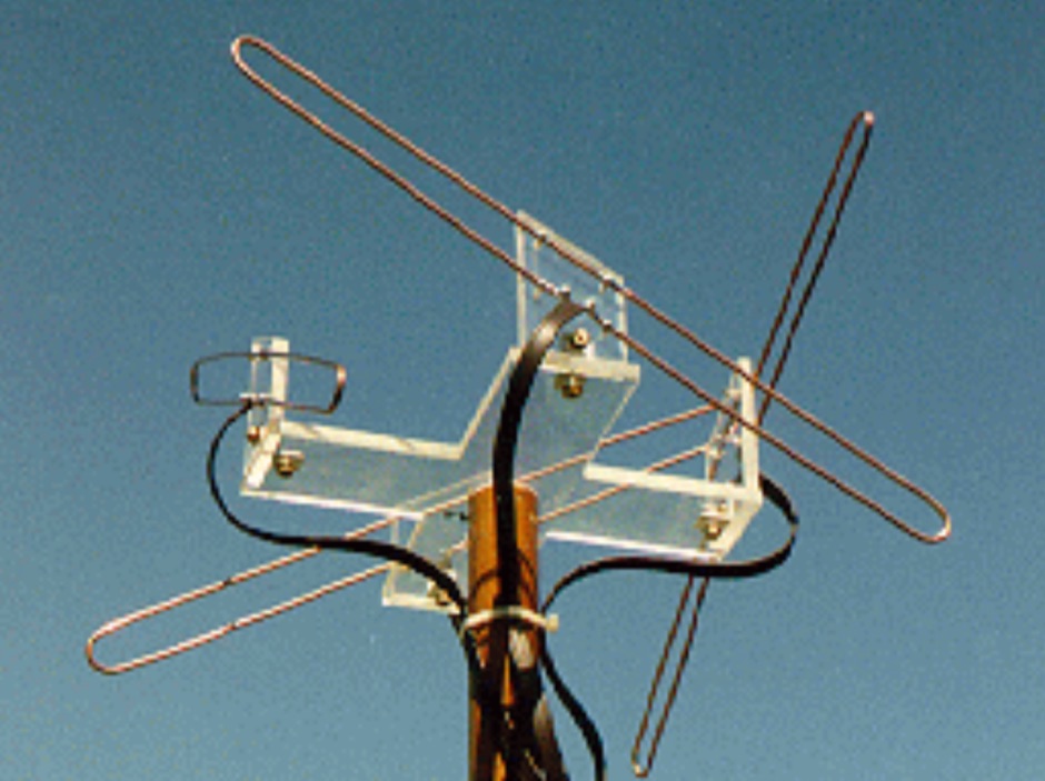
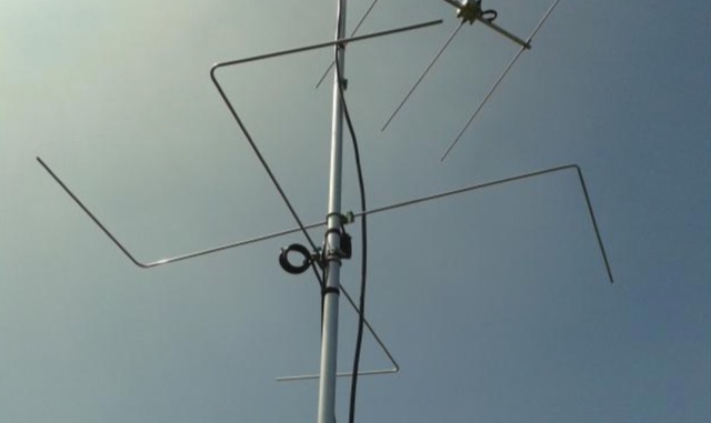
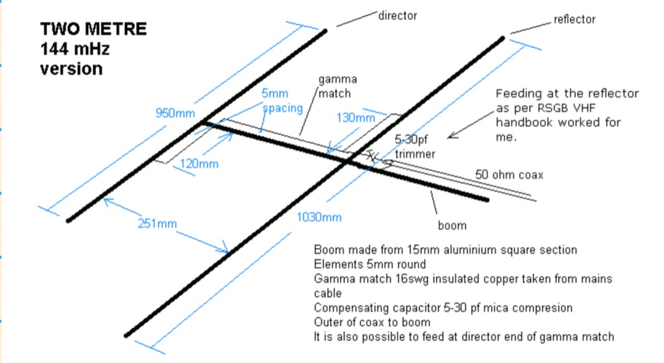 The HB9CV is a well known two element antenna of a directional beam type with a forward gain of 4 to 5 dBd. This one is for two metres but it can be scaled, from the dimensions in the diagram, for other bands I have also made them for four and six metres
 -
 VectorFox is a software born to incorporate a PC into the fox hunting environment. VectorFox is able to take inputs from up to 5 sources, such as a 2m beam, a 2m signal meter, a TDOA, etc, and display the results on the screen. VectorFox also accepts Agrelo inputs. From these results the operator can choose which indication is best and have a line drawn on the map in the direction of the signal.
 -
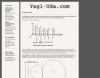 The Yagi-Uda antenna, information on basic design, project and measure of Yagi-Uda antenna, include free repository/sample of beam antenna.
 -
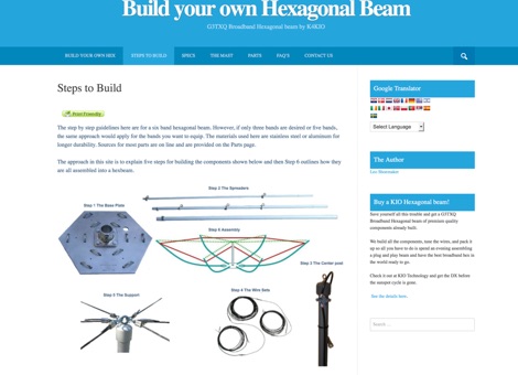 A web site dedicated to hex beam homebrewing. The hexagonal beam has become a wildly popular antenna. It is a directional antenna that provides great performance and does not require a full scale, expensive tower.
 -
 A fractional bandwidth of up to 30:1 characterizes spiral antennas, making them highly effective across a very wide frequency range, often from 1 GHz to 30 GHz. The resource details two primary types: the **Log-Periodic Spiral Antenna** and the **Archimedean Spiral Antenna**, defining each with specific polar functions and illustrating their planar configurations. It explains that spiral antennas are typically circularly polarized, with a Half-Power Beamwidth (HPBW) of approximately 70-90 degrees, and a peak radiation direction perpendicular to the spiral plane. The content elaborates on critical design parameters affecting radiation, including the total length (outer radius) for lowest frequency, the flare rate ('a' constant) for optimal radiation versus capacitive behavior, the feed structure (often an infinite balun) for high-frequency operation, and the number of turns (typically 1.5 to 3 turns). It also discusses the theoretical impedance of 188 Ohms for Log-Periodic spirals, derived from Babinet's Principle, noting actual impedances are often 100-150 Ohms. The article presents a simple construction method for an Archimedean spiral, demonstrating VSWR and efficiency measurements. Measurements from a constructed spiral antenna show a VSWR that is fairly constant across the band, albeit with a mismatch loss of about 3 dB. The antenna efficiency remains around -5 dB (31.6%) across its operating range, indicating a decent wideband radiator despite opportunities for optimization.
 -
 Constructing a compact directional antenna for the 17-meter band, this resource details the build process for a Moxon rectangle, a two-element Yagi variant with folded-back elements. It covers the antenna's evolution from the _VK2ABQ beam_ and provides specific dimensions for a version built using fishing pole whips. The content includes a discussion of the antenna's radiation pattern, feedpoint impedance, and its inherent front-to-back ratio, which is often superior to a standard two-element Yagi. Practical considerations for element spacing and material choices are also addressed, alongside a visual representation of the antenna's physical layout. Performance data presented includes a comparison showing the Moxon rectangle's **2.5 dB gain** over a half-wave dipole and a front-to-back ratio of **20 dB**. The resource also touches upon the antenna's relatively wide bandwidth for a two-element beam and its suitability for portable operations due to its compact footprint. It offers insights into optimizing the design for specific operating conditions and discusses the advantages of its lower take-off angle compared to omnidirectional wire antennas, making it effective for DX contacts on the 17-meter band.
 -
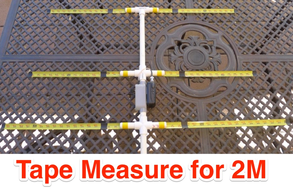 A Tape Measure Beam Antenna for Radio Direction Finding based on WB2HOL design.
 -
 This Antenna project is a bit more complex than other omni antennas for satellite use, but it is much easier and cheaper than a standard tower mounted circular polarized azimuth and elevation rotating beam system.
 -
 Horizontal polarized omni directional 50MHz Antenna. This antenna is intented to use in a contest station as a second system beside the stacked yagi beam system. An omnidirectional systeem can be an advantage when it comes to short openings on wich the operator must react quickly.
 -
 A hexagonal beam is a form of the Yagi antenna which is based on parasitic principles developed early in the last century in Japan for achieving gain in one direction.How HexBeam antennas works. A hexagonal beam operates exactly like Yagi antenna, but instead of a driven element that is straight like a dipole, it is a wire bent into the shape of the letter M.
 -
 2 Wavelength ,2 Meter Bi-Square Beam , 5dbd gain. This antennas are very cheeap to build and their radiation pattern is similar to a figure 8 with maximum signal through the loop but they may be used as a near-omnidirectional antenna
 -
 Method, Units of Measure, and the Dipole Standard of Reference. This article helps in understanding where does beam gain come from in directional aerials like in example Yagi antennas.
 -
 This page provides detailed information on the 4DX directional wire beam antenna designed by LZ1AQ, LZ1ABC, VK6LW, and DD5LP. It explains how to create this antenna for single or multiple bands using four separate sloping wires. The page includes instructions on achieving directionality, gains, and F/B ratios, as well as generating radiation patterns, VSWR charts, antenna currents diagrams, and Smith charts. It is a valuable resource for hams interested in building and optimizing their own directional wire beam antennas for improved performance and long-distance contacts.
 -
 Phased array antennas are composed of multiple individual antenna elements that can have their phase and amplitude controlled to steer the main beam direction in real-time. They are used in radar, communications, and electronic warfare, and offer improved gain and reduced side lobes. A comprehensive document on Phased Arrays include techniques to increase the Antenna Gain and change the Radiation Pattern
 -
 Learn how to design a Hentenna antenna, a portable asymmetrical double-loop antenna ideal for amateur HF or VHF bands. This page provides details on constructing and optimizing the antenna for maximum performance in DX communications. Discover how altering the antenna's vertical feed section can adjust the VSWR resonant frequency and how changing the support pole's position can alter the beam direction. Originally developed by Japanese 6-meter operators, the 'Hentenna' offers a unique design that allows for horizontal polarization when vertically oriented. Explore radiation patterns, VSWR charts, and antenna currents diagrams to optimize your antenna's performance for long-distance contacts.
 -
 This DIY Yagi costs less than 20 Dollars, and let you increase the performance of your connection. With this project you can build a better Yagi beam antenna resonant on 850MHz, a 8 element yagi directional antenna
 -
 This article presents a novel Top Loaded End-Fed Half-Wave (TLEFHW) antenna design for 20-meter ham radio operation. The antenna features a compact 14-foot vertical radiator with a capacitance hat configuration, eliminating the need for radials or ground systems. Using EZNEC modeling and field testing, the design achieves a 1.5:1 SWR across the 20m band with a 4.11 dBi gain. Key features include quick deployment, lightweight construction, and directional radiation pattern with 110-degree beamwidth. The design, while requiring a 45-foot footprint due to the top hat, offers an effective portable solution for amateur radio operators seeking a no-ground, no-tuner 20m antenna option.
 -
 This article discusses the design and implementation of a 2-element wire beam antenna for the 20 meter band, suitable for field day operations with 4 Switchable Directions. The antenna is configured with sloped wires in an inverted V shape, with a specific design to achieve directional properties. The author tested the antenna design using MMANA and NEC2 software, based on a solution published in QST. Detailed diagrams and instructions are provided for constructing the antenna on top of a 12 meter mast, with specific wire lengths and positioning to ensure optimal performance. This resource is valuable for hams looking to build a directional antenna for the 20m band and improve their field day setup.