Search results
Query: mmana
Links: 18 | Categories: 0
-
 MM Antenna Analyzer by JE3HHT Makoto Mori based on the moment method, which was introduced in MININEC. Download MMANA Free from this page that offer download of basic version and link to the MMANA pro version.
 -
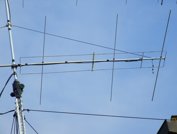
 This document details the design and construction of a Vinecom 6N4 dual-band Yagi antenna for the 50MHz (6-meter) and 70MHz (4-meter) amateur radio bands. The antenna features 9 total elements (4 elements for 50MHz, 5 elements for 70MHz) on a 4.236-meter aluminum boom. Computer simulations using MMANA software predict 7.21 dBd gain on both bands with front-to-back ratios of 16.01dB (6m) and 15.37dB (4m). The design uses 12.7mm diameter elements mounted on a 32mm square boom, weighing 5.7kg total. Practical measurements with an MFJ-269 analyzer confirmed good SWR performance across both bands after element length adjustments.
 -
 The utility "NEC-2 for MMANA" is intended for calculation of antenna models made and optimized in program MMANA and for construction and simulation of antenna models using input language NEC-2 and based on MMANA models.
 -
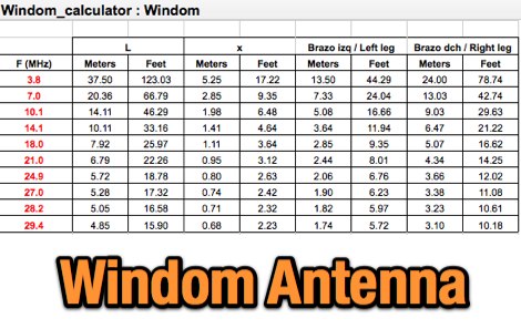 This article describes the characteristics of the Windom antenna and shows the results of several simulations made with MMANA-GAL, covering models optimized for the 20 m, 40 m and 80 m bands.
 -
 This article describes the design and simulation of a multiple dipole antenna for the HF band, using the software MMANA-GAL. The antenna will be designed to operate in the 10, 20, 40 and 80 m bands
 -
 A 2 elements delta loop antenna for 14 MHz with a MMana simulation file, dimensions, pictures of this aluminium tube based delta loop antenna, and matching system details.
 -

-
 A delta loop antenna for 20 meters band designed with MMana with a tuning system made in a classic stub configuration
 -
 A Yagi-Mag antenna for the 4 meters band with NEC and MMANA files plans and pictures
 -
 A simple dipole for 40m band feeded with 450-Ohm openwire feedline includes MMANA Gal files to download
 -
 A top band shortened vertical antenna project. This project includes drawing and MMANA-GAL output screens.
 -
 The page provides information on a simple 50MHz J-Pole Antenna project based on the DK7ZB design. It explains the principle of the Wireman-J-Pole, the feeding process, practical mounting, and simulation results using MMANA GAL. The content aims to guide amateur radio operators in building their own J-Pole antennas for the 6-meter band.
 -
 Learn how to design and analyze a folded trifilar antenna for the 80-meter band. Based on a description from RAF antennas between 1940 and 1970, this article provides step-by-step guidance on modeling the antenna, calculating resonance frequency, adjusting dimensions, and verifying performance. Perfect for hams looking to improve their antenna setup for better transmission and reception on the 80M band.
 -
 Andrew Georgakopoulos, SV1DKD, modeled the End-Fed Half Wave (EFHW) antenna using MMANA-GAL software. He evaluated the EFHW-8010-2K from Myantennas.com for field operations, comparing it to random wires, OCFD, and dipole antennas. His results showed similar performance to OCFD, confirming EFHW's practical feeding advantage but with potential high-voltage risks at the feed point
 -
 AutoEZ, Automated use of EZNEC, is an Excel workbook that works alongside EZNEC antenna modeling software version 5.0 or later. With AutoEZ, you can control different aspects of your model using variables and run multiple EZNEC test cases automatically. Formulas in Excel allow you to modify any part of the model. AutoEZ's interface resembles EZNEC's. Enabling macros in Excel might be necessary before using AutoEZ. The program opens various model file formats including EZNEC (.ez), NEC (.nec or .inp), AO and NEC/Wires (.ant), and MMANA-GAL (.maa). You can set the frequency and/or variable values for the test cases to be run through EZNEC. AutoEZ allows you to create animations showcasing how the pattern changes as the model configuration is modified. You can download a fully working, but limited demo copy from this site.
 -
 Chavdar Levkov, LZ1AQ, presents an experimental comparison of small wideband magnetic loops, building on his previous work on wideband active small magnetic loop antennas. His research focuses on increasing loop sensitivity by maximizing the short-circuit current, which is directly tied to the "loop factor" M = A/L, where A is the equivalent loop area and L is its inductance. Levkov's methodology involves reducing inductance and increasing area through parallel or coplanar crossed (CC) configurations, comparing these designs against a reference single quad loop of 1 m2 area. Experimental verification included testing three distinct loop types: a simple quad loop, two coplanar crossed (CC) loops, and eight parallel loops, all designed to have a total geometric area of 1 m2. Measurements were conducted at 1.8, 3.5, 7, and 10 MHz using a small transmitter 270 meters away, with a Perseus direct sampling receiver for precise signal level assessment. The results consistently showed that CC loops, particularly Loop 5 (two CC circular loops with 1.44 m2 total area), yielded significantly higher currents, up to 9.1 dB over the reference loop at 3.5 MHz, validating M as a reliable predictor of loop sensitivity. Numerical simulations using MMANA further corroborated the experimental findings, demonstrating an almost perfect correlation between the calculated M factor and the induced loop current for 15 different loop models. Levkov concludes that CC loops offer superior sensitivity for a given loop area, while parallel loops are advantageous for minimizing physical volume. Practical recommendations suggest using loops with an M factor greater than 0.5 uA/pT for quiet rural environments, and he provides a spreadsheet tool, WLoop_calc.xls, to aid in optimizing loop configurations for specific operational needs.
 -
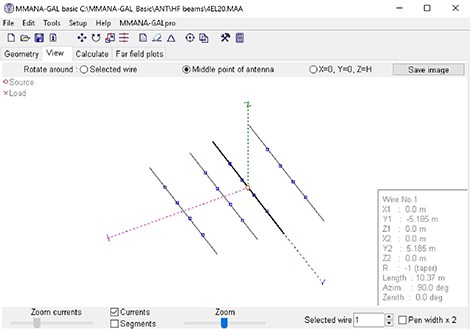
 This article discusses the design and implementation of a 2-element wire beam antenna for the 20 meter band, suitable for field day operations with 4 Switchable Directions. The antenna is configured with sloped wires in an inverted V shape, with a specific design to achieve directional properties. The author tested the antenna design using MMANA and NEC2 software, based on a solution published in QST. Detailed diagrams and instructions are provided for constructing the antenna on top of a 12 meter mast, with specific wire lengths and positioning to ensure optimal performance. This resource is valuable for hams looking to build a directional antenna for the 20m band and improve their field day setup.
 -
 This page provides a detailed example of the modeling and analysis of an 80m delta dipole antenna with a 600-ohm bifilar feedline. The model is based on antennas used by the RAF from 1940 to 1970. It covers the original model specifications, conductor mass calculations, resonance frequency observation, geometry adjustment steps, and final antenna dimensions. The content includes theoretical formulas, resonance frequency calculations, and practical steps for adjusting the antenna for optimal performance. Overall, it serves as a practical guide for hams looking to understand and optimize the performance of a delta dipole antenna for the 80m band.