Search results
Query: CW receive
Links: 60 | Categories: 0
-
 The 222 MHz Transverter project, based on Zack Lau's (W1VT) original July 1993 QEX magazine design, provides an IF of 28 MHz for both transmit and receive paths. Rick Bandla (VE3CVG) contributed supplemental notes and construction details, including modifications to achieve 10 mW output power from an initial 4 mW PEP. The design incorporates three distinct boards: a Local Oscillator (LO), a Transmitter (Tx), and a Receiver (Rx), with an estimated parts cost of just over $150 CDN, significantly less than commercial kits. Construction involves both through-hole and surface-mount components, with specific guidance on mounting MAV and MAR devices, grounding techniques, and component selection. The project details include parts lists, schematics for the LO, Tx, and Rx, and board layouts. Troubleshooting advice emphasizes sequential testing, starting with the LO, then Tx, and finally Rx, using a 194 MHz and 222.100 MHz capable FM handheld for signal tracing. Further enhancements are discussed, such as an optional Tx driver stage to boost output to 100 mW and the potential modification of a Motorola Maxor 80 PA for 222 MHz SSB/CW operation. The resource also covers practical aspects like power attenuation pads for IF radios (e.g., FT817) and considerations for enclosure design, including repurposing a Maxor 80 case. Performance reports indicate successful 70 km contacts with only 4 mW output.
 -
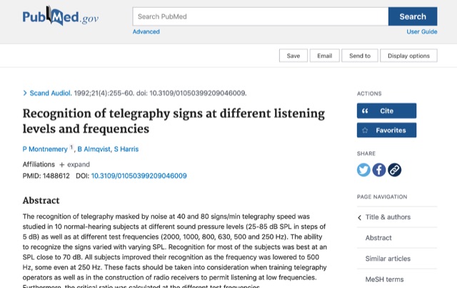 The recognition of telegraphy masked by noise at 40 and 80 signs/min telegraphy speed was studied in 10 normal-hearing subjects at different sound pressure levels (25-85 dB SPL in steps of 5 dB) as well as at different test frequencies (2000, 1000, 800, 630, 500 and 250 Hz). The ability to recognize the signs varied with varying SPL. Recognition for most of the subjects was best at an SPL close to 70 dB. All subjects improved their recognition as the frequency was lowered to 500 Hz, some even at 250 Hz. These facts should be taken into consideration when training telegraphy operators as well as in the construction of radio receivers to permit listening at low frequencies. Furthermore, the critical ratio was calculated at the different test frequencies.
 -
 This article details the design and construction of a compact 20-meter QRP SSB transceiver by Pete Juliano, N6QW, measuring just 2 x 4 x 2 inches—small enough for a shirt pocket. Inspired by a 1963 QST design and refined from a prior version, it employs bilateral circuits, a 4.9152 MHz homebrew crystal filter, switched-crystal VXO for 60 kHz coverage (14.160-14.220 MHz), and standard components like ADE-1L mixers and IRF510 PA for 1W output. Key innovations include a double-sided PCB skeletal frame for shielding and isolation, Vectorboard sub-assemblies, and ultra-miniature relays. The bilateral receiver/transmitter shares stages, omitting AGC for simplicity, while a W3NQN LPF and optional 10W external amp enable DX contacts. Tune-up focuses on crystal matching and bias for linearity. Videos on YouTube demonstrate performance, confirming excellent stability and audio. Total cost nears $100, prioritizing portability over features like CW.
 -
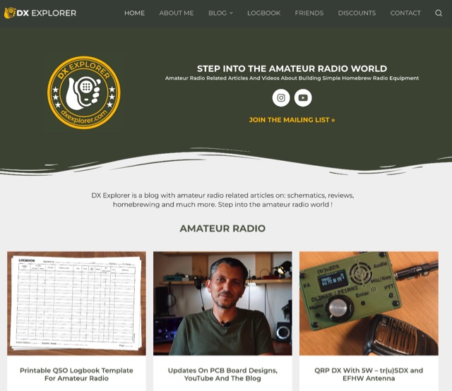 The _DX EXPLORER_ blog serves as a personal chronicle of amateur radio experiences, particularly emphasizing homebrew projects and DIY radio equipment. It provides insights into constructing various transceivers and receivers, such as the Minimalist CW Transmitter and the Sputnik Regenerative Receiver, offering practical guidance for those new to the hobby. The content often details the assembly and operation of low-cost kits like the $3 Pixie Transceiver, demonstrating accessible entry points into radio construction. Beyond building, the site also features reviews of commercial gear, including the Tidradio TD-H8 Radio, providing an operator's perspective on performance and utility. The author, YO6DXE, shares a learning journey, aiming to inspire fellow enthusiasts to engage with the technical aspects of amateur radio. This resource covers a range of topics from basic circuit explanations to practical operating tips, fostering a deeper understanding of radio principles. The blog's focus on personal experimentation and project documentation makes it a relevant resource for hams interested in hands-on learning.
 -
 Integrating a _Software Defined Radio_ (SDR) into an existing ham radio setup involves connecting it with a standard transceiver (TRX), power amplifier (PA), and antennas. The core component is a splitter box that facilitates the connection between the TRX and the SDR, allowing for simultaneous operation without modifying existing equipment. In receive mode, the splitter ties the antenna inputs of both the TRX and a direct conversion receiver (DC RX) together. During transmission, the DC RX input is grounded via a fast telecom relay controlled by the transceiver's -SEND signal, incorporating a 10ms delay for safety. The splitter box includes a 3.7 dB input attenuator for impedance matching and acts as a protective fuse for the DC RX input. Ground loops are mitigated using common mode balun transformers, while the DC RX input is insulated with a broadband transformer. An audio switch box complements the setup, enabling users to listen to either the main transceiver, the SDR output, or both simultaneously. This configuration ensures noise immunity and safety, with the splitter housed in a screened box made from PCB material. On-air tests, such as the CQ WW 160m CW DX Contest, demonstrate the system's effectiveness, showcasing the SDR's ability to handle crowded band conditions with superior selectivity and dynamic range. The SDR's narrow bandwidth filters and waterfall display provide significant advantages, allowing operators to detect weak signals amidst strong interference. The integration of SDR with conventional radios offers enhanced operational flexibility and performance in challenging environments.
 -
 DXLog.net Cluster functions as a dedicated client application designed to enhance DXLog.net contest logging operations. It facilitates simultaneous connections to multiple DX cluster nodes, providing a consolidated view of DX spots. The software also supports integration with local CW skimmers, enabling real-time reception of CW signals and their automatic decoding into spots. The utility broadcasts UDP data across the local area network, allowing DXLog.net to receive and process these spots efficiently. A key feature includes CAT control integration, which automatically QSYs connected CW skimmers to the frequency of interest, optimizing spot acquisition. The system also incorporates duplicate spot filtering to reduce redundancy and offers blacklist management for unwanted callsigns or frequencies. Programmable commands and dynamic skimmer bandwidth control further refine its operation, adapting to varying band conditions and contest strategies. Automatic reconnection capabilities ensure continuous operation, maintaining reliable access to DX information crucial for competitive contesting.
 -
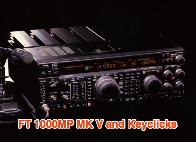 YaesuFT1000MK V stands out with improved close-spaced SSB transmit performance, reversing a trend seen in other modern radios. Featuring a class-A mode, it offers clean HV finals when kept out of ALC. However, two significant flaws persist: the noise blanker causes receiver IM distortion, and the transmitter lacks wave-shaping on CW, resulting in pronounced keyclicks. Preliminary tests reveal strong keyclicks +1kHz and -1kHz, prompting a combined modification to address both issues.
 -
 The **Yaesu FRG-100** shortwave receiver, introduced in 1992, operates across a frequency range of 50 kHz to 30 MHz, accommodating AM, LSB, USB, and CW modes, with an optional narrow-band FM capability. Its physical dimensions are 238 x 93 x 243 mm, with a weight of 3 kg, making it suitable for both portable and fixed station deployments. Power options include standard mains voltage or 12VDC, providing operational flexibility for diverse listening environments. The front panel integrates a manual tuning knob, an analogue signal strength meter, and an LCD display that provides critical information such as frequency, operating mode, memory channel, and time. Users can configure various operational parameters, including tuning steps and bandwidth filters, to optimize reception for specific signals. This review highlights the FRG-100's straightforward interface and its utility for shortwave listening enthusiasts. The design emphasizes user-friendly adjustments for settings, which contributes to its appeal among those interested in general coverage reception.
 -
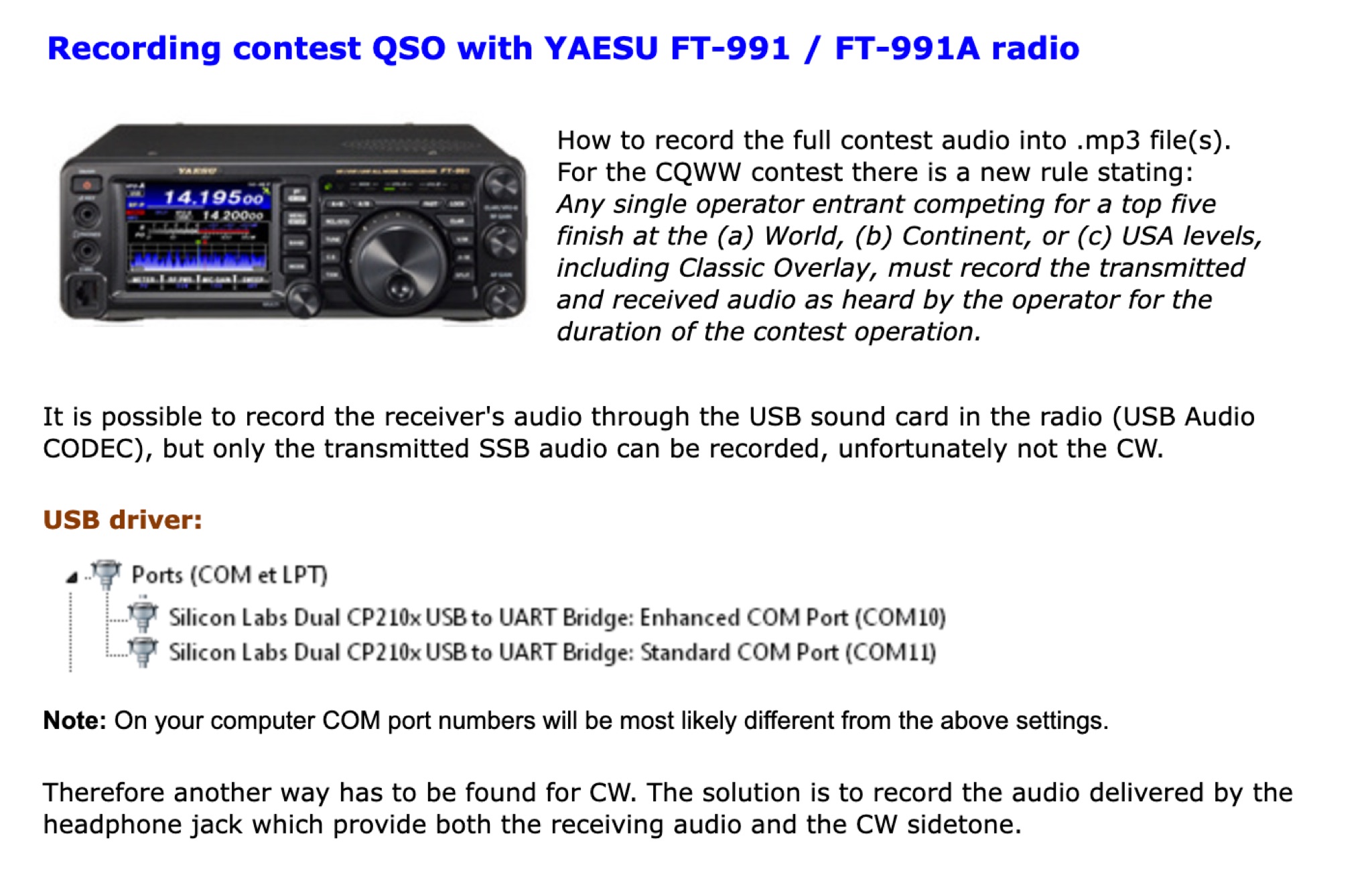 How to record the full contest audio into .mp3 file(s). t is possible to record the receiver's audio through the USB sound card in the radio (USB Audio CODEC), but only the transmitted SSB audio can be recorded, unfortunately not the CW.
 -
 Early 20th-century transatlantic wireless communication efforts involved distinct technical approaches by Reginald Fessenden and Guglielmo Marconi. Marconi's systems, operational until approximately 1912, primarily utilized _spark technology_ for wireless telegraphy, facilitating Morse code communication between ships and across oceans. His Poldhu station in December 1901 radiated signals in the MF band around 850 kHz, later evolving to 272 kHz in October 1902, and eventually 45 kHz by late 1907 with increasingly larger antenna structures like the pyramidal monopole and capacitive top-loaded arrays. Fessenden, conversely, focused on _continuous wave transmission_ for wireless telephony, recognizing its necessity for speech. His transatlantic experiments in 1906 employed synchronous rotary-spark-gap transmitters and 420-foot umbrella top-loaded antennas at Brant Rock, MA, and Machrihanish, Scotland, tuned to approximately 80 kHz. Fessenden later utilized the _Alexanderson HF alternator_ at 75 kHz by late 1906 for pure CW transmission, integrating a carbon microphone for amplitude modulation. Receiver technology also differed, with Marconi initially relying on untuned coherer-type detectors, later developing the magnetic detector in 1902, while Fessenden's CW approach necessitated more advanced detection methods.