Search results
Query: choke
Links: 106 | Categories: 2
-
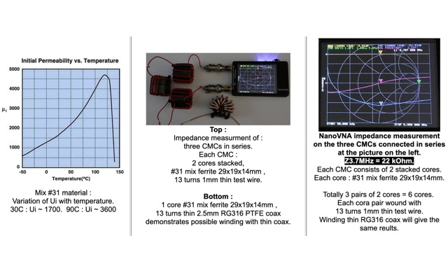 The influence of temperature changes in Common Mode Chokes. To get an indication of the impedance behavior when the core temperature changes, the author tested a CMC by heating it with a hairdryer, and measuring its temperature with an infrared thermometer. When the CMC temperature rises from 30C to 90C, the frequency of maximal impedance shifts down from ca.10 MHz to ca.7.2 MHz, or by a factor 1.4.
 -
 This article describes the design and construction of a 4-meter band vertical sleeved dipole antenna, built to complement a newly acquired Yaesu FTDX10 transceiver. The simple yet effective antenna consists of modified coaxial cable housed in weather-resistant plastic conduit, featuring an integrated 8-turn choke coil. Despite common misidentification as an EFHW antenna, this design is actually a sleeved dipole that provides an excellent 50-ohm match across the band, achieving SWR values between 1:1 and 1.1:1. The project demonstrates an economical approach to entering the relatively quiet 4-meter band.
 -
 Constructing a 4:1 Guanella current balun involves cross-connecting two 1:1 current baluns. At the low-impedance end, transmission lines from each balun are connected in parallel, while at the high-impedance end, they are connected in series. This configuration allows the device to achieve a 1:4 impedance ratio, effectively transforming a 200-ohm load to 50 ohms. The balun described utilizes **FT240-43 toroids** wound with 2.5mm2 twisted pair cable for 8 turns, intended for use with a 20m **Deltaloop antenna**. Measurements performed with a 200-ohm resistor demonstrate satisfactory VSWR and impedance characteristics across the HF bands. The article compares the performance of 2.5mm2 cable versus 1mm enameled wire, recommending the former for superior efficiency. Emphasis is placed on maintaining short core-terminal connections to optimize performance. Additional considerations include the option of integrating a separate Common Mode Choke (CMC) for enhanced common mode current suppression, especially if the balun's inherent suppression is not prioritized.
 -
 Constructing a **J-Pole antenna** from 450 Ohm ladder line for 2-meter (144 MHz) and 70-centimeter (440 MHz) operation involves specific calculations and assembly steps. The design, based on an earlier KD6GLF concept using 300 Ohm twinlead, features a ¾ wavelength radiator and a ¼ wavelength matching stub, functioning as an end-fed half-wave antenna without requiring ground radials. It offers a gain of 2.4 dB over isotropic. The resource provides the formulas for determining the lengths of the ¾ wave radiator and ¼ wave stub, incorporating a velocity factor of 91% for 450 Ohm ladder line. For 146 MHz, the radiator measures 55 3/16 inches and the stub 18 3/8 inches. Construction details include cutting a 57¾-inch piece of ladder line, stripping 4 inches from one end, and attaching a 24-inch section of RG58 or RG8X coax with a 3-5 turn RF choke. SWR adjustment is achieved by sliding a shorting bar or by incrementally trimming the elements at a 1:3 ratio (stub to radiator). The goal is a 1:1.1 SWR at 146 MHz, which typically yields 1:1.2 at 446 MHz. The article also discusses power handling, noting that while 10-15 watts is fine, 50 watts may increase SWR to 1:2.1, and advises keeping the antenna away from other objects to prevent coupling and SWR degradation.
 -
 A common mode choke/balun, essential for mitigating common mode current on antenna feedlines, is detailed in this construction and measurement guide. It utilizes eight Fair-Rite #2643167851 Mix 43 ferrites housed within a Hammond 1598JSGYPBK plastic case, with RG-8X coax cable forming the windings. The document references design principles from Ian White, GM3SEK's article on cost-effective ferrite chokes. Specific construction details include the layout of three coils to minimize inter-coil coupling and methods for securing the ferrites with foam tape. The resource presents comprehensive measured data, including isolation impedance (magnitude, real, and imaginary components), Q factor, inductance, and phase angle across various frequencies. It also covers the choke/balun's coax frequency response and return loss characteristics. Techniques for measuring choking impedance are thoroughly explained, focusing on S21 transmission measurements with a Vector Network Analyzer (VNA) and testing ferrite beads in both S11 and S21 modes. The guide describes a practical setup using an aluminum sheet or baking foil for measurements and outlines the calculation of series impedance from attenuation in a 50-ohm system. Additionally, it details a method for determining the balun's equivalent L and C around resonance by adding a parallel capacitor.
 -
 Understanding how radio frequency interference (RFI) is coupled into equipment and subsequently detected is crucial for amateur radio operators. This guide delves into the fundamental mechanisms of RFI, particularly focusing on detection at semiconductor junctions and the unintended antenna action of system wiring. It explains that most RFI detection follows a square law, meaning a 6 dB reduction in RF signal can result in a 12 dB drop in detected audio, offering a practical approach to mitigation. The resource also clarifies the concept of common mode versus differential mode signals, detailing how cable imperfections can convert common mode antenna current into differential signals. It addresses the critical "Pin 1 Problem" in audio interfacing, a common design flaw where cable shields connect to the circuit board instead of the shielding enclosure, leading to significant RFI issues. Practical solutions, such as proper shielding, using twisted-pair cables, and strategic bonding of equipment, are discussed to effectively reduce or eliminate RFI. The guide emphasizes the importance of proper filtering and the often-misunderstood concept of "ground" in electrical systems, distinguishing between earth ground, equipment ground, and circuit common. It provides insights into minimizing loop area in wiring to reduce inductively coupled noise and antenna action, drawing on the author's extensive engineering background and ham radio experience.