Search results
Query: 70 cm
Links: 154 | Categories: 2
-
 This resource details the construction and performance of a compact broadband magnetic loop antenna designed for portable receiving applications with devices like the _ATS MiniRadio_. The antenna utilizes approximately 3 meters of 0.5–1 mm copper wire wound in two turns on a rhomboidal wooden frame, measuring 50 cm by 70 cm. It connects via a modified 9:1 unun, where the primary center tap is isolated from ground to improve common-mode noise rejection. The design provides untuned operation across a frequency range from the longwave band up to approximately 25 MHz. Performance characteristics include observable directivity for noise suppression and the ability to connect directly to a radio or via a 50 coaxial cable for remote operation. The article specifies the unun's 3:1 turns ratio and its SMA output for connectivity. The methodology focuses on practical construction and observed reception quality.
 -
 Presents detailed expedition charts and statistics for the **XX9W** DXpedition, covering operating time, total QSOs, unique calls, and duplicate QSOs. The resource provides comprehensive band and mode breakdowns, including FT8, SSB, CW, and FM, across 80m, 40m, 30m, 20m, 17m, 15m, 12m, 10m, 6m, 2m, and 70cm. Users can access DXCC statistics by band and mode, daily QSO totals, and multiband QSO statistics. Continent-by-mode and continent-by-band breakdowns are also available, detailing activity from Africa, Asia, Europe, North America, Oceania, and South America. The platform also tracks the expedition's impact on user totals, showing new band, new mode, new band + new mode, new slot, and new DXCC contacts.
 -
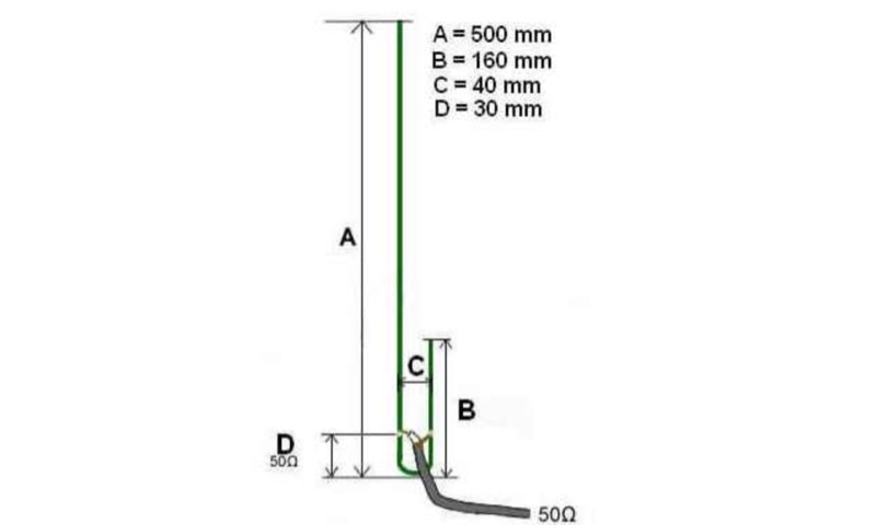 The UHF J-Pole antenna described here utilizes an aluminum angle bar and 4mm galvanized threaded rod for its construction, with dimensions based on a previously published design. Assembly involves drilling the angle bar, securing threaded rod sections with nuts, and connecting the coaxial cable via cable lugs, ensuring the braid connects to the shorter element. ROS adjustment is achieved by manipulating nuts approximately **30mm** from the angle bar, allowing for fine-tuning of the impedance match. Once optimal tuning is established, _super glue_ is applied to seal the coaxial cable ends and protect the threaded rod cuts from corrosion, enhancing durability. This project emphasizes rapid realization with common hardware, providing a practical solution for radio amateurs seeking a simple yet effective antenna for the 70cm band.
 -
 For amateur radio operators seeking resilient, off-grid communication, the _MeshCom_ firmware provides a robust solution for text-based messaging over a mesh network. Utilizing LoRa modulation and the APRS protocol, this firmware is designed for low-energy consumption and cost-effective hardware, primarily operating in the 70cm band. Nodes, identified by amateur radio callsigns, can send short text messages to all participants or directly to specific callsigns, functioning as repeaters to extend network reach. The system supports automatic status and position messages, with optional sensor data for WX-Data and Telemetry. MeshCom nodes can be configured as gateways to HAMNET or the internet, enhancing connectivity options. The project emphasizes a self-building and self-healing mesh network architecture, crucial for emergency communication scenarios. Operating frequencies include 433.175 MHz (EU, USA, Africa), 439.9125 MHz (UK), and 433.925 MHz (Norway). The firmware is compatible with hardware platforms such as ESP32/LoRa modules, RAK-WISBLOCK, and ESP32-DEV4/E22-LoRa, offering a flexible deployment for various amateur radio applications.