Search results
Query: yagi 3 ele
Links: 283 | Categories: 2
-
 Online antenna calculator for a basic 3 elements yagi uda directional antenna. The described antenna design offers a front-to-back ratio of at least 20 dB, a gain exceeding 7.3 dBi, and a bandwidth (SWR < 2) of approximately 7% around the center frequency. It has an input impedance of 50 ohms when using a straight split dipole, which can be substituted with a folded dipole of the same length, increasing the impedance to 200 ohms. A matching balun is required for coaxial feeder connection, and the boom should be made of a dielectric material, like wood.
 -
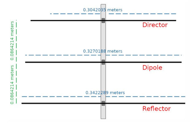 This article describes the phases for the construction of a Yagi antenna. The calculations of the parameters are made using 4NEC2 software. This type of antenna is used for transmissions and receptions of electromagnetic waves. The project shown here refers to the frequency of 433.92 MHz.
 -
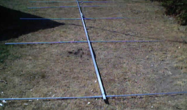 This is a design based on the QuickYagi 4 software by WA7RAI with some changes for practical reasons. The beam uses 6.5 metres of standard 25mm square boom, 12mm diameter elements without tapers. The actual boom length used is 6.3 metres and all parts are readily available.
 -
 This DIY guide details constructing a 5-element Yagi antenna for VHF frequencies. Yagi antennas offer directional signal transmission/reception compared to omnidirectional ones. The guide covers material selection (aluminum, screws, etc.), design using software or formulas, and step-by-step assembly including cutting elements, drilling holes, and attaching the coaxial cable. While calculations are provided for a 146 MHz design, adjustments are necessary for different frequencies. Safety precautions and potential result variations are emphasized.
 -
 The multiband tuned doublet, or center-fed Zepp, is a simple and efficient HF antenna that operates effectively across most amateur bands using a balanced parallel-wire feedline and antenna tuner. Unlike coax-fed dipoles, it tolerates impedance mismatches with minimal loss. By selecting suitable feedline and dipole lengths, one can achieve stable multi-band operation. While it doesn’t match monoband Yagis, it offers excellent performance, low cost, and broad coverage. Its radiation pattern and efficiency vary with frequency, but it remains a practical and versatile solution for HF operators.
 -
 A selection of technical articles and analysis offering guidance and insight to enable you to recognise and build your own high performance yagi design.
 -
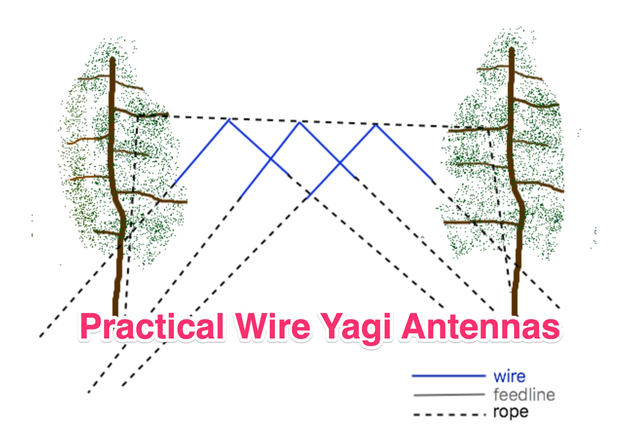 Learn how to build wire Yagi antennas for your ham radio setup. Discover how smaller wire elements can offer practical and portable options for temporary operations. Explore designs like the Hex Beam, Spider Beam, and Moxon that require less mechanical complexity and can be easily rotated or supported. Find out how to construct and hang wire Yagis from ropes, trees, or masts with inverted vees or horizontal elements. Get tips on element positioning, gain, and beamwidth considerations. Follow simple construction steps using a rope boom and marking element positions for efficient assembly. Enhance your ham radio experience with versatile wire Yagi antennas.
 -
 This project introduces the Loggi, a hybrid antenna merging the wide frequency coverage of log-periodic dipole arrays (LPDA) with the high gain and front-to-back ratio (F/B) of Yagi antennas. Traditional LPDAs span broad frequencies with moderate gain and low VSWR, while Yagis provide high gain and F/B over narrow bands. By analyzing high-Tau LPDA designs, it was found they could nearly match the gain of VHF/UHF Yagis while maintaining excellent patterns, F/B, and front-to-rear ratios (F/R). Optimizing specific elements for target frequencies (e.g., 144.1 MHz) led to the Loggi, which uniquely features all driven elements without passive directors or reflectors. This design effectively functions as a narrowband optimized LPDA, with front elements acting like Yagi directors and rear elements like Yagi reflectors, thus enhancing gain and directional characteristics while retaining broad frequency versatility.
 -
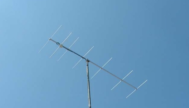 A home made project for a 7 element yagi antenna for the two meters band based on the DK7ZB original desing.
 -
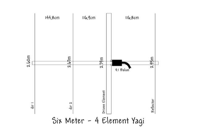 A 4 element Yagi Antenna for six meters band
 -
 Showcasing German engineering, ANjo Antennen develops and manufactures a diverse portfolio of amateur radio and commercial antenna products. Their offerings span a wide frequency range from 1.8 MHz to 3000 MHz, emphasizing electrical and mechanical precision for longevity. The company actively participates in events like FUNK.TAG Kassel, providing opportunities for direct engagement and order pickup. ANjo's product line includes high-performance **Yagi antennas** optimized for Tropo and EME, along with multi-stacked Quad antennas designed for contest operations, featuring wide horizontal and narrow vertical beamwidths. They also produce circularly polarized satellite antennas, some with switchable LHCP/RHCP, leveraging their commercial satellite antenna expertise. Beyond amateur applications, ANjo provides flexible, custom antenna solutions for commercial sectors such as BOS, EMC measurements, and telemetry. Their commitment to quality is evident in the Premium-Line antennas, which utilize **1.4301 (V2A) stainless steel** for mast clamps and connectors, ensuring durability and corrosion resistance. They also offer end-fed HF multiband wire antennas, known for their compact footprint and discreet installation.
 -
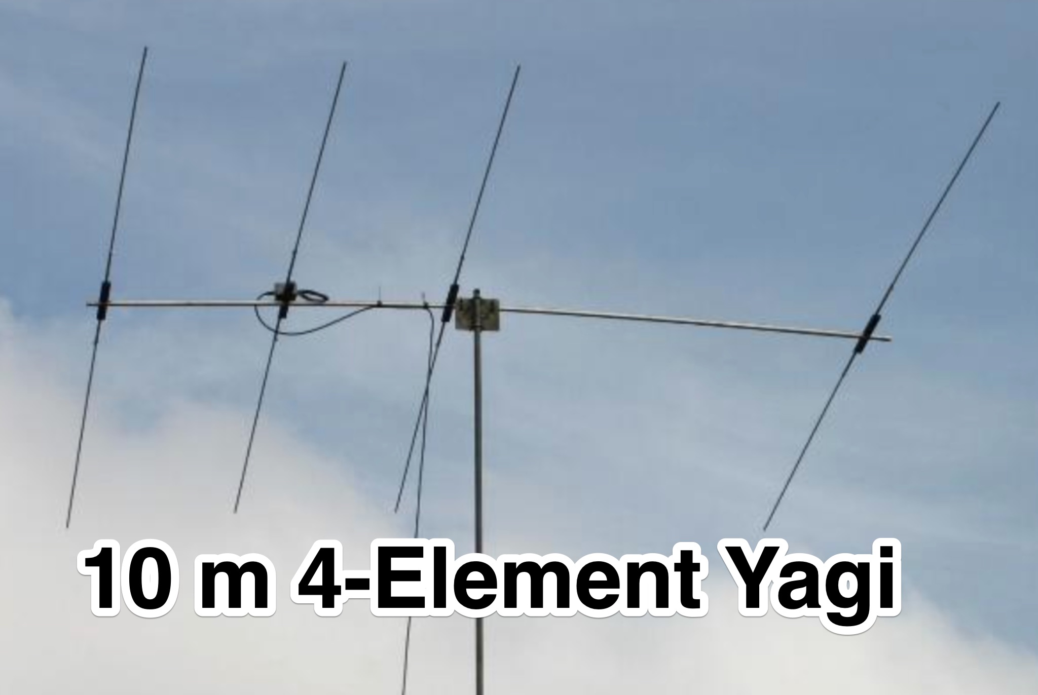 This page provides construction details for a 4-element 10-meter Yagi antenna with 28 Ohm impedance. It includes information on the elements, positions, diagrams, and data related to frequency, gain, front-to-rear ratio, radiation resistance, SWR, and loss. The content is aimed at hams or radio operators interested in building and optimizing Yagi antennas for the 10-meter band.
 -
 This is a plan for an optimized element UHF Yagi Antenna for UHF Bands featuring a 9dBd forward gain, a 13 dB front-back ratio, and a bandwith of 10 MHz on the 430-440MHz range.
 -
 Optimizing directional gain on the 40-meter band often involves complex antenna designs; this resource details the construction and performance of a reversible _Moxon_ array. The design provides directional coverage from southeast to west, with a switching mechanism to reverse the pattern towards east to northwest. Key design considerations include precise element spacing, the critical role of coil inductance for proper resonance, and the use of _NEC5_ for accurate electromagnetic modeling, ensuring the antenna performs as predicted across the desired frequency range. The antenna's performance is evaluated through on-air contacts, demonstrating effective signal propagation to regions like the Caribbean, South/Central America, the US, and Europe. The article presents measured SWR plots and gain patterns, comparing them against the _NEC_ model predictions to validate the design's efficacy. Practical application notes cover mounting considerations and the benefits of its reversible pattern for targeted DXing on 40 meters, offering a robust solution for operators seeking enhanced directional capabilities without a full-sized rotating Yagi.
 -
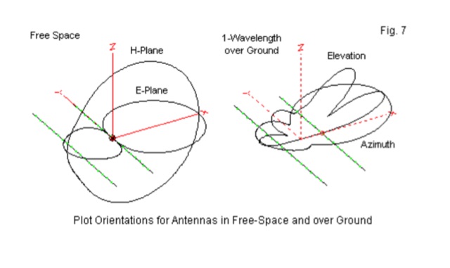 Method, Units of Measure, and the Dipole Standard of Reference. This article helps in understanding where does beam gain come from in directional aerials like in example Yagi antennas.
 -
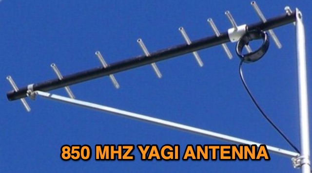 This DIY Yagi costs less than 20 Dollars, and let you increase the performance of your connection. With this project you can build a better Yagi beam antenna resonant on 850MHz, a 8 element yagi directional antenna
 -
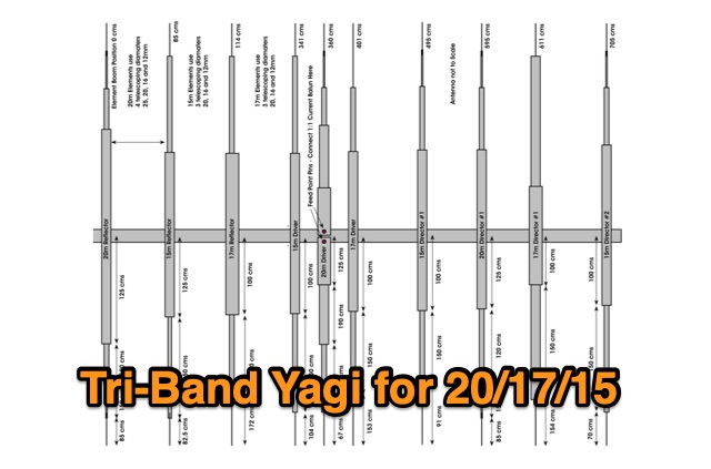 A cost-effective alternative to the Optibeam OB10-3W, a high-performance but expensive tri-band Yagi antenna for the 20, 17, and 15-meter bands. The original Optibeam, featuring three full-size elements on each band, delivers strong forward gain and front-to-back ratio but comes with a high price tag. To address this, a custom design was developed, offering similar performance at a fraction of the cost. Using accessible materials and a simple 1:1 current balun, the homemade version proved highly effective, making it a practical solution.
 -
 This page discusses the construction and design of a shortened 2-element Yagi antenna for the 40-meter band, focusing on the driven element. The author shares insights on adding hats to the coil to reduce losses and improve performance. The article also mentions the use of EZNEC modeling software and an AIM4170 analyzer for tuning. Amateur radio operators interested in such antenna design and optimization for the 40-meter band can find useful information and practical tips on this page.
 -
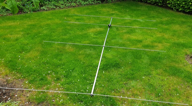 A project for a six meters Yagi beam antenna, built mainly for portable operations. This is a 4 element Yagi beam with a 4 meters boom.
 -
 Paul McMahon details the design and construction of a four-element Yagi antenna for the 50-52.5 MHz range, published in Amateur Radio Magazine (Dec 2011). The antenna, featuring a raised driven element and a capacitive/DC connection using copper strips, maintains consistent VSWR and performance despite two years of weather exposure. The design utilizes inexpensive plumbing conduit for the boom and provides detailed construction guidelines, parts lists, and performance analysis through 4NEC2 simulations.
 -
 The 2m 7 element Yagi antenna is a perfect beam antenna with 11dB gain and a front-to-back ratio of 20-25 dB. It has seven elements and requires a matching network built of 3/8" aluminum tubing and RG-8 cable. The gamma tube is adjusted to provide the best fit, and the gamma-driven element feeding clamp is tightened. If the beam is vertical, a non-conducting mast is utilized to prevent detuning and skewing of the radiation pattern. For optimal VHF operating, the antenna is installed at a height of 30 feet or higher.
 -
 145 MHz is the target frequency for this 2-meter Skeleton Slot Yagi Stack antenna project. The design focuses on feeding two stacked Yagi antennas using a skeleton slot radiator, which is a unique approach for VHF enthusiasts. The project details the construction process, including the loop tapered matching section for impedance matching, ensuring optimal performance. The use of specific components like the EH789 element holder and MB456 main mast bracket is highlighted, providing clarity on the assembly process. The construction utilizes 20x20 box aluminum bar for durability and precision. Key dimensions, such as the element length (ER-ED4) and main boom spacing (MM123), are meticulously outlined. This attention to detail aids in replicating the antenna design accurately. The downloadable PDF offers comprehensive instructions, making it accessible for amateur radio operators interested in VHF antenna construction. This project is particularly beneficial for those looking to optimize their 2-meter band operations. The inclusion of a skeleton slot radiator and loop tapered matching section demonstrates advanced techniques in antenna design, catering to both intermediate and advanced builders.
 -
 Operating on the 60m band requires specialized antennas, and the 2 Element HB9CV, also known as the _ZL special_, excels in this domain. With a gain of **7.3 dBi** when phased at a 162-degree shift, it rivals traditional 3-element Yagi antennas, making it a solid option for enhancing 60m operations. The construction process is thoroughly detailed, providing insights into its performance and practical applications. Real-world comparisons demonstrate that the HB9CV antenna outperforms long Beverage antennas by an average of **5.5 dB** in reception, showcasing its effectiveness in various conditions. Insights from Mr. Cebik's analysis further validate its design, confirming its capability to maximize communication on the 60m band.
 -
 A small Yagi antenna for camper van. It is made of aluminum tubing, breaks down for storage, and works well for communicating with others. He built it in an afternoon and it gets good signal. The antenna is lightweight and can be packed up to fit inside his van while traveling
 -
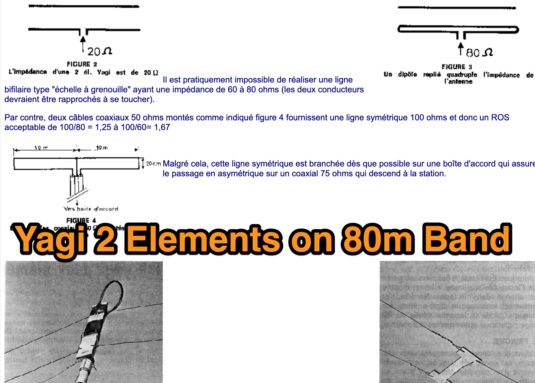 This article from the July 1976 issue of Radio REF discusses the trend of large antennas for ham radio operators on the low bands. It specifically focuses on a Yagi 2 element antenna for the 80m band, detailing its construction and functionality. The author explains how the antenna can be switched between directing signals towards the West or East using a switch at the station. The article also provides technical details on the lengths of the director and reflector elements, and how they impact the antenna's performance. A useful resource for hams looking to build or understand Yagi antennas for the 80m band.
 -
 Presents the design and construction of a folding 5-element Yagi antenna specifically engineered for 144 MHz portable operation, particularly for VHF contest Rover categories. It details element dimensions, boom construction using ¾-inch pine, and a folding mechanism that reduces the 52-inch boom to 26 inches for transport. The document provides a table with precise element distances and lengths, including a 2.4 mm length correction for solid parasitic elements, and specifies the use of 3/16-inch solid aluminum for parasitic elements and brass tubing for the driven element. It also covers the bent dipole driven element design for impedance matching, balun implementation with Type 31 ferrite beads for common mode current suppression, and weatherproofing for the feed point. The resource includes predicted performance data from 4NEC2 modeling, showing SWR and return loss characteristics, as well as gain and front-to-back ratios at various frequencies across the 2-meter band. It reports a measured SWR of 1.2:1 at 144.2 MHz and 1.5:1 at 147 MHz, corrected for 25 feet of RG-8/M coaxial cable loss. The design offers approximately 1.5 dB more gain than a previous 4-element design, maintaining a decent SWR up to 147 MHz, and was successfully deployed in a winning June 2016 ARRL VHF Contest Rover entry.
 -
 YAGio 1.01 is a Windows-based software for designing DL6WU long Yagi antennas on VHF and UHF frequencies. It supports Windows 2000, XP, Vista, 7, and likely 8. Using keyboard commands, users input specifications such as frequency, gain, and element diameters, and YAGio generates the design. You can download latest Yagio version from this page. Results can be saved in YIO, NEC, YAG, MMA, and YC6 formats, or printed directly.
 -
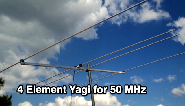 Guide to constructing an effective antenna for 50MHz. Inspired by a design from Martin DK7ZB, the article emphasizes the importance of precise measurements and quality materials. With a 2.20m boom and careful assembly, the antenna promises excellent performance, resilience, and cost-effectiveness, making it ideal for six meter band operations.
 -
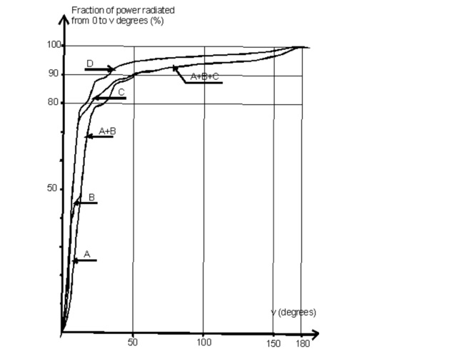 This paper by Leif Asbrink (SM 5 BSZ) presents a practical approach to designing very high gain Yagi antennas, focusing on the "brute force" optimization method. The method, described in a previous article, ensures convergence independent of initial guesses. The paper provides detailed tables of element lengths and positions for Yagi antennas optimized for 144.1 MHz with a 50-ohm feed point impedance, aiming for minimal losses and high accuracy in comparisons.
 -
 Demonstrates a specific impedance matching technique for resistive loads ranging from 22.2 to 45 ohms, connecting them to a 50-ohm transmission line. The method employs series sections of 50-ohm and 75-ohm coaxial cables, with graphical data illustrating the required cable lengths (L1 and L2) in wavelengths for a perfect match. This approach is particularly useful for feeding **vertical** and **Yagi antennas**. The resource provides a practical example of matching a 25-ohm Yagi antenna at 50.150 MHz, specifying the use of RG-58C/U (50 ohms) and RG-59B/U (75 ohms) cables, both with a 66% velocity factor. It calculates the precise physical lengths in centimeters and inches for the required cable sections. Additionally, the document briefly discusses integrating a balun at the load end, suggesting methods such as coiling a cable section or utilizing ferrite beads to create a W2DU-type balun. The presented methodology offers a clear, data-driven solution for common antenna impedance challenges.
 -
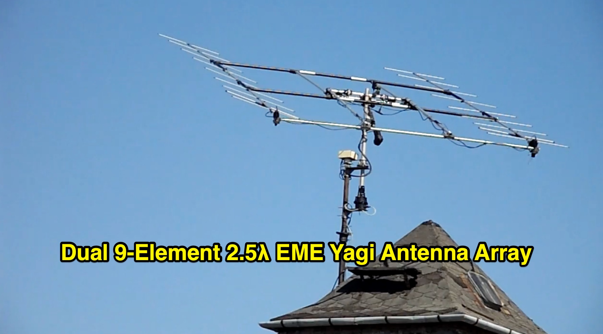 This project describes a high-performance EME antenna array consisting of two home-designed 9-element Yagis, each about 2.5 wavelengths long, combined into a 25-ohm system and matched to 100 ohms using 9/4λ sections of 50-ohm coax. The array supports rotatable polarity from 0° to 180°, allowing both horizontal and vertical polarization to optimize moonbounce performance under varying conditions. Despite operating for years without a balun—something another designer called “disastrousâ€â€”the system has delivered strong results, including copying very weak DX such as VK3KH at about -25 dB with only 120 W (around 2 kW ERP). The builder continues to refine the mechanics, having installed new gear motors and an upgraded follow-up control system in 2011.
 -
 SAT filters ensure effective full-duplex satellite QSOs by mitigating interference between 145 MHz uplink and 435 MHz downlink signals. Custom coaxial and SMD-based filters address transmitter harmonic interference and improve receiver isolation, achieving over 70 dB suppression in the undesired band. Designed for simplicity, these filters maintain optimal VSWR and are housed in shielded brass enclosures. Practical implementations with Yagi antennas demonstrate compatibility with SDR systems, enabling seamless communication even in challenging satellite conditions, such as low-elevation passes and DX pile-ups.
 -
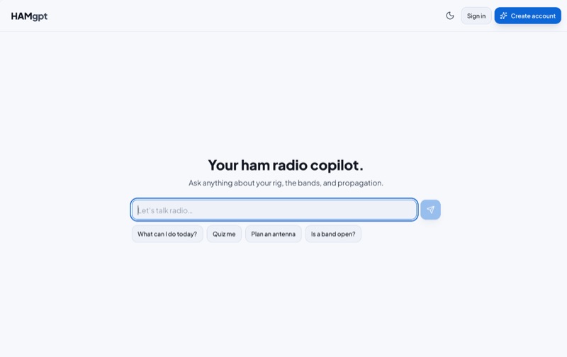 HAMgpt offers a personalized amateur radio experience, leveraging AI to provide real-time operational guidance. It integrates live propagation data, current band conditions, and operator-specific context, including callsign, QTH, license class, and station equipment, to deliver relevant answers. The system can identify open HF, VHF, and UHF bands, suggest workable DXpeditions and POTA/SOTA activations, and provide accurate repeater offsets and CTCSS/DCS tones for local repeaters. Unlike general-purpose chatbots, HAMgpt avoids fabricating frequencies or license privileges, instead relying on actual data for its responses. It supports antenna design calculations for various types like Yagi, dipole, vertical, and magnetic loop antennas, offering to-scale dimensions. The platform also assists with license exam preparation and provides satellite pass predictions tailored to the user's location. It supports multiple countries, including the United States (FCC Technician, General, Extra), Canada, the United Kingdom, Australia, Japan, and Argentina, incorporating their specific band plans and power limits.