Search results
Query: allen tx
Links: 7 | Categories: 0
-
 About 1 to 1 current balun by Roy Lewallen, W7EL
 -
 The article details a specific method for performing maintenance on a crank-up tower, focusing on cable and rotator replacement without a full power pulldown. It outlines the necessary equipment, including a 2-section extension ladder with a horn attachment and a two-piece, 6-foot steel pipe, specifying a 1 1/4-inch diameter. The procedure involves lowering tower sections onto the internal pipe to slacken cables, allowing for their removal and replacement, and also describes how to replace the rotator while the tower remains upright. Key steps involve using the pipe to support tower sections, enabling access to the cables and bearings. The author, N5AR, emphasizes safety by instructing the reader to remain on the ladder at all times, rather than climbing the tower itself. The process is presented as manageable for a single operator, with the author having successfully completed the task on a _UST TX472_ tower. Specific tools mentioned include Allen wrenches and end wrenches for cable ends and bearing bolts. The method provides a practical approach for tower upkeep, minimizing the complexity often associated with such tasks and allowing for maintenance of components like cable pulleys and their bearings.
 -
 Operating the _Icom IC-746_ HF/VHF transceiver often presents specific technical questions, and this resource compiles a comprehensive Frequently Asked Questions (FAQ) document in an ASCII text format. It details common inquiries and solutions related to the rig's functionality, accessories, and potential modifications. The content is structured into distinct sections addressing general information, power supplies, antennas, microphones, keyers, amplifiers, TNC integration, and optional IF filters. The FAQ provides practical guidance on topics such as configuring the internal automatic antenna tuning unit (ATU), selecting appropriate power supplies, and understanding microphone pin-outs. It also delves into advanced subjects like computer control via CI-V, wiring for PSK31 operation, and troubleshooting common issues like low S-meter readings on 2m FM or loose tuning shafts. Specific questions cover the installation of optional IF filters, comparing Inrad versus Icom filters, and optimizing filter combinations for various modes. Furthermore, the document outlines various hardware and firmware modifications, including those for increasing monitor volume, replacing LCD driver transistors, and implementing a "poor man's TCXO." It even touches upon untested modifications, such as replacing PIN diodes in the demodulator. The FAQ also lists manual errata and discrepancies, offering a robust knowledge base for IC-746 owners seeking to optimize their station or resolve operational challenges.
 -
 Developing operational amateur radio equipment for the 134 GHz band presents significant technical challenges, particularly in frequency generation and stability. This resource details the construction of a 134 GHz system, outlining its architecture with separate transmit (Tx) and receive (Rx) modules, each employing a local oscillator (LO) and RF head units. The system utilizes a dual Flann 50 GHz lens-type horn antenna configuration for optimal signal coupling. The transmit path incorporates an LMX2541 synthesizer chip operating at approximately 2.8 GHz, referenced by a 10 MHz double-oven Morion OCXO for exceptional stability. This signal is multiplied through a series of stages (X4, then X2) to generate a 22.4 GHz signal, which subsequently drives a dual series diode multiplier to produce the final X6 signal for 134 GHz operation. The receive side features an anti-parallel diode mixer coupled to a 144 MHz transceiver via a preamplifier, ensuring effective downconversion. Operational mode is CW, achieved by keying a multiplier stage. The project includes images of the Tx and Rx head units and describes a successful 3.5 km test with G8ACE, demonstrating stable signal tones due to PLLs locked to OCXOs at both ends, confirming the system's robust performance.
 -
 DF0WD/DL4YHF's Longwave Overview details amateur radio operations on the 135.7 to 137.8 kHz segment in Germany. The author outlines the "inofficial" European band plan, specifying segments for QRSS, TX tests, beacons, conventional CW, and data modes. Early LF activities at DF0WD began with a 20-watt CW transmitter, later upgraded to a homemade linear transverter capable of 100 watts, driven by an Icom IC706 on 10.137 MHz. The station's antenna system includes a 200-meter wire, approximately 10 meters above ground, supported by football field light-masts. Despite its length, the antenna's efficiency is noted as very low due to the immense wavelength of about 2.2 km. The author's experience highlights the significant challenge of achieving effective radiated power (EIRP) on LF, estimating DF0WD's EIRP at around 80 milliwatts based on field strength measurements from PA0SE. DF0WD/DL4YHF has successfully worked numerous countries on 136 kHz CW, including DL, F, G, GI, GM, GU, GW, HB9, HB0, LX, OE, OH, OK, OM, ON, OZ, PA, and SM. The author also mentions ongoing efforts to log contacts with CT, EI, LA/LG, and to complete a two-way QSO with Italy, demonstrating persistent activity on this challenging band.
 -
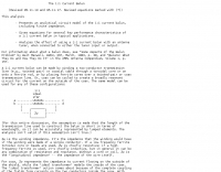
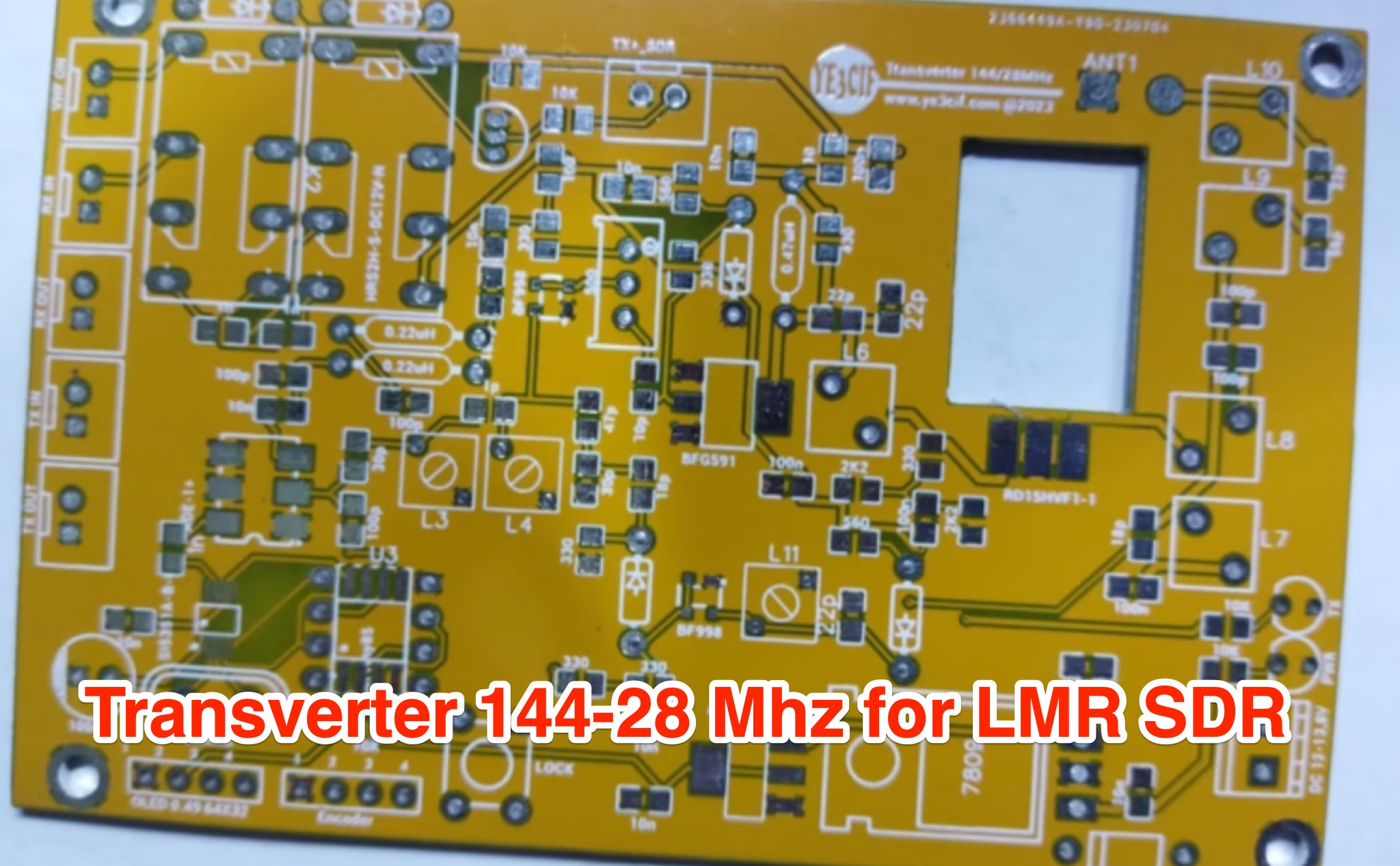 Learn how to build a VHF 144MHz transverter connected to an LMR SDR radio using easily accessible components. The transverter works by mixing the 144Mhz input frequency with a 116 MHz local oscillator frequency. Explore the challenges of finding a 116 MHz crystal and the solution of using a programmable Si5351A oscillator. Follow the provided schematic for the RX and TX sections. The transverter design is still a work in progress, with ongoing trials to achieve optimal results.
 -
 TX5EU 2026 DXpedition to Raivavae Island, **OC-114**, within the Austral Islands, providing a detailed account of the German/Dutch team's operations. The resource outlines the participation of operators such as DL2AWG Guenter, PA2KW Evert, and DK2AMM Ernoe, who engaged in CW, SSB, RTTY, and various digital modes. It documents the real-world challenges encountered, including significant equipment failures and antenna damage to 80/60m, 30m, and 10m verticals due to adverse storm conditions. The page offers timely news updates on the expedition's progress, noting repairs to a power amplifier's 10/12m bandpass filter, which enabled three stations to utilize amplification. Earlier reports highlighted power failures and the loss of multiple power amplifiers, necessitating one station to operate barefoot FT-8 with 100W. The team's persistent efforts to repair antennas as weather permits are also detailed, reflecting the dynamic nature of remote island operations.