Search results
Query: amplifier schematics
Links: 19 | Categories: 6
-
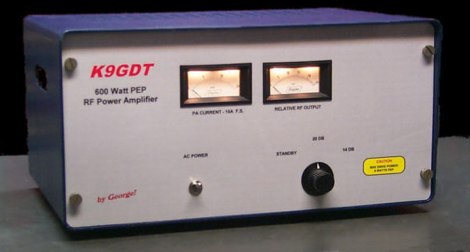 Schematics plans by K9GDT and all infos to build a 600 Watt HF Amplifier. The amplifier uses four Motorola MRF150 50 volt TMOS power FETs configured in push-pull/parallel and biased for class AB linear operation.
 -
 K9AY loop antenna installed at PA6Z Contest group. This is a receiving antennas for the low bands (160m, 80m and 40m). Include schematics and info on a building the control box, preamplifier and low-pass filter
 -
 813 Linear Amplifier Project includes many schematics, drawind and assembling construction
 -
 50 MHz 1500 Watt Russian GS35B amplifier. Well documented. Complete construction details,pictures,schematics, and more.
 -
 Dealer for Cb radios, Cb antenna & accessories Galaxy radio, Cobra cb radio, Ranger, Texas Star, Palomar. Police scanner, radar detector, GPS, GMRS, FRS, Wilson cellular amplifier & antennas. Owners manuals, schematics and links.
 -
 WV7U YC156 and 3CPX800 amplifier projects. See pictures, schematics, test data, links, and more!
 -
 Based on Motorola MRF454, schematics and component list
 -
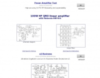
 Infomration schematics and pictures about various hf and vhf QRO linear amplifiers
 -
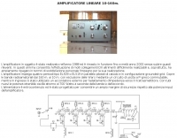 Italian page including pictures schematics diagrams of an home made linear amplifier using four EL509 in parallel. Output power is about 700W.
 -
 Demonstrates the construction of a **homebrew spectrum analyzer** designed by Wes Hayward, W7ZOI, and Terry White, K7TAU, enabling radio amateurs to build a capable test instrument without significant expense. The resource details a _double-conversion superheterodyne_ circuit, employing intermediate frequencies of 110 MHz and 10 MHz, and covers essential blocks such as the time base, logarithmic amplifier, resolution filters, and local oscillators. It highlights the use of hybrid and monolithic ICs, including mixers, amplifiers, and VCOs, to simplify construction while maintaining performance. The design supports useful measurements in the 50 kHz to 70 MHz range, with methods outlined for extending capabilities into VHF and UHF. The authors emphasize that this analyzer, while simple to build, is intended for serious measurements, requiring careful control of signal levels to avoid spurious responses. It uses an oscilloscope for display, with specific instructions for calibration and adjustment of various stages, including the log amplifier and IF gain. The guide provides detailed schematics and component lists for each section, such as the 110 MHz triple-tuned band-pass filter, which achieved **90 dB** image rejection, a significant improvement over double-tuned circuits. Practical advice on alignment and troubleshooting is included, drawing on the authors' extensive experience in RF circuit design.
 -
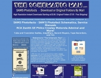 Sams Photofact downloads - Schematics and Service Manuals for Radios, Amplifiers, More
 -
 Advanced QRP Low Cost Mosfets HF Linear Amplifier with schematics, IMD, gain data and more. Six articles about amateur radio.
 -
 The FL-2100Z amplifier referenced in the following images is the 6-Band model covering 10m thru 160m (no WARC bands) and not the 9-Band version that included the WARC bands. Modifications, schematics and manual
 -
 An RF power supply for 144 MHz schematics and instructions
 -
 A pdf file with schematics of an ssb and cw filter AF amplifier
 -
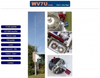 WV7U's YC156 and 3CPX800 amplifier projects. Everything you wanted to know about using the YC156 or 3CPX800 in a ham radio linear amplifier. See pictures, schematics, test data, links, and more!
 -
 This article loaded with nice pictures and schematics, describes a 160-10 meter linear amplifier that uses a pair of 3-500Z triode power tubes. It was designed and constructed by William Moneysmith, W4NFR. The amplifier features fast warm up and 1500-Watt RF output with 100-Watts of drive.
 -
 Mark Connelly, WA1ION article on Medium Frequency Amplifier Circuits in PDF format, include some RF amplifier schematics
 -
 This is a power amplifier project for a RF 600W 1.8 MHz to 70 MHz linear amplifier including a Low Pass Filter. Projects includes schematics, pictures, PCD design, fans details, note on PA ferrite chokes and assembling instructions