Search results
Query: best dipole antenna
Links: 10 | Categories: 0
-
 Build a space efficient trapped dipole antenna for 40-80-160 meter bands using RG-58 and PVC pipe. The document provides a brief guide on building a compact dipole antenna appropriate for the 40, 80, and 160-meter amateur radio bands. It explains the materials, building processes, and tuning methods required to provide best performance while preserving space. The paper also discusses theoretical elements of dipole antennas, such as impedance matching and feedline selection.
 -
 GM4JMU shortened dipole for 40 meters band. This article illustrates in detail how to build a resonant antenna for 7.030 MHz. Cut two 10.25-meter pieces of insulated wire, wind 40 turns of wire onto plastic tubing, and connect the wire to a central insulator using a choke balun built of RG174AU coax and a ferrite toroid. Once built, the antenna is adjusted by altering the wire length to produce the lowest Standing Wave Ratio (SWR) for best performance. The guide emphasizes careful building and adjustment for the best results.
 -
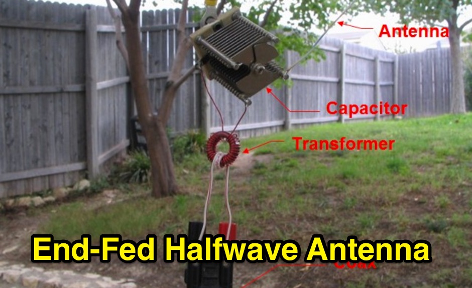 The end-fed halfwave antenna is a resonant half wavelength long antenna like a dipole antenna except for it is fed at its end rather then in the center. This antenna is as old as radio and is probably best known as the Zepp Antenna
 -
 The best antenna is the simple Dipole. If you have height, you even can put up a quarter wave vertical or an inverted, but sometimes you may need shorten version by 4S7NR
 -
 The simple dipole is perhaps the best antenna for consistent performance. Basic page on dipoles by G3PTO
 -
 The ZS1J/B beacon operates on 28.2025 MHz with 5 Watts output to a half-wave, end-fed vertical antenna, initially installed in 1977 as ZS5VHF near Durban. The 10-meter transmitter is a modified 23-channel CB radio, and the identification keyer uses a diode matrix unit with TTL ICs from the same era. After relocation to Plettenberg Bay in 1993, the beacon has been in continuous service, with additional QRP transmitters later installed for other bands. In 1994, a single-transistor, 80-meter, 0.5-watt QRP transmitter with a half-wave dipole was added on 3586 kHz, followed by a 160-meter, 0.5-watt unit on 1817 kHz. A 30-meter, 0.5-watt transmitter was installed in 1996, operating on 10.124 MHz. In 2002, a 40-meter QRRP beacon on 7029 kHz, with an output of 100 microwatts, achieved DX reports up to 1100 km from ZS6UT in Pretoria. Best DX reports for the 80m and 160m beacons came from 9J2BO.
 -
 The article describes the construction of a 1:49 impedance transformer designed to match the high impedance (around 2500Ω) of an end-fed half-wave (EFHW) dipole antenna to the 50Ω impedance of a typical transceiver. The EFHW is a popular portable antenna due to its simple construction, but feeding it can be challenging compared to a center-fed dipole. The transformer was built using an FT240-43 ferrite toroid core, with 2 primary and 14 secondary windings for a 1:49 impedance ratio. A capacitor was added in series with the primary winding to improve performance at higher frequencies. The author compared versions with one and two cores, and found that 100pF worked best for the single core design while 200pF was optimal for the dual core transformer.
 -
 The article details the design and construction of a four-band Moxon beam by a radio amateur. The beam, mounted atop a rooftop tower, aimed for gain over a dipole on 20 meters, cost under $500, and included additional bands. The design features fiberglass spreaders, four bands (20/15/10/6 meters), and a single feedpoint. The construction involved computer modeling, NEC source code, and specific dimensions. The article outlines the assembly, materials, and tuning process, including in-situ adjustments for optimal performance. Despite initial challenges, the beam improved signal strength and facilitated contacts on multiple bands, marking it as the best HF antenna the author has owned.
 -
 Antenna patterns are all about interference. Presentation on wire antennas for HF bands. Dipoles, horizontal and vertical dipoles, effects of ground on radiation patterns, multi-band wires antennas. Knowing what you should expect from the radiation patterns for waves on your wires will help you choose what will work best for your needs. The principles of interference can lend insight into what to expect from a wire antenna.
 -
 This presentation on antennas is a practical guide for amateur radio operators. The key takeaway is that the best antenna for your station depends on your constraints and goals. There is no magic solution and buying a wire antenna is not recommended as it might be expensive and not as effective. The presentation covers different antenna types including dipoles, verticals, Yagis and loop antennas. Important factors to consider when choosing an antenna include SWR, feeder types, and whether you need a balun. The author emphasizes that ATUs don’t improve a poor antenna and advises against obsessing over SWR readings.