Search results
Query: broadband loops
Links: 4 | Categories: 0
-
 You will find on these pages my experiences and results on antennas and local/non-local QRM/noise reduction. Using a broadband vertical active magnetic loop and a home made / designed broadband amplifier. Two vertical magnetic Alford loops are used in an array. Analog and Digital Signal Processing and a dual phase coherent Software Defined Radio (SDR) are used. By PA0SIM
 -
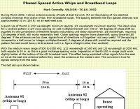 Phased Spaced Active Whips and Broadband Loops by WA1ION
 -
 Integrating a _Software Defined Radio_ (SDR) into an existing ham radio setup involves connecting it with a standard transceiver (TRX), power amplifier (PA), and antennas. The core component is a splitter box that facilitates the connection between the TRX and the SDR, allowing for simultaneous operation without modifying existing equipment. In receive mode, the splitter ties the antenna inputs of both the TRX and a direct conversion receiver (DC RX) together. During transmission, the DC RX input is grounded via a fast telecom relay controlled by the transceiver's -SEND signal, incorporating a 10ms delay for safety. The splitter box includes a 3.7 dB input attenuator for impedance matching and acts as a protective fuse for the DC RX input. Ground loops are mitigated using common mode balun transformers, while the DC RX input is insulated with a broadband transformer. An audio switch box complements the setup, enabling users to listen to either the main transceiver, the SDR output, or both simultaneously. This configuration ensures noise immunity and safety, with the splitter housed in a screened box made from PCB material. On-air tests, such as the CQ WW 160m CW DX Contest, demonstrate the system's effectiveness, showcasing the SDR's ability to handle crowded band conditions with superior selectivity and dynamic range. The SDR's narrow bandwidth filters and waterfall display provide significant advantages, allowing operators to detect weak signals amidst strong interference. The integration of SDR with conventional radios offers enhanced operational flexibility and performance in challenging environments.
 -
 This article explores the powerful features of AutoEZ as an Excel application working with EZNEC antenna modeling software. The article demonstrates how variables, equations, and formulas enable versatile antenna design and automatic optimization. Through practical examples including dipoles, inverted vees, delta loops, and monopoles, the author shows techniques for achieving resonance, implementing transmission line resonators for broadbanding, and optimizing antennas across frequency ranges. The step-by-step demonstrations cover unit conversion, coordinate calculations, segmentation considerations, and SWR optimization. This practical guide illustrates how AutoEZ extends EZNEC's capabilities, making complex antenna modeling more efficient and accessible.