Search results
Query: channel 16
Links: 14 | Categories: 0
-
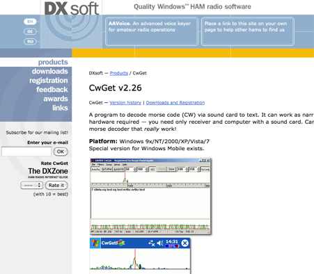 CwGet v2.55 is a software application for amateur radio operators designed to decode Morse code (CW) signals into text using a standard computer sound card, eliminating the need for specialized hardware. The program features a customizable interface with a spectrum display for visualizing signal frequencies and peaks, an oscillogram for monitoring signal presence and setting detection thresholds, and a received symbols window for displaying decoded text. Key functionalities include Automatic Frequency Control (AFC) to lock onto signals, adjustable FIR and IIR filters for noise reduction, and a burst filter to mitigate short noise impulses. It also supports automatic CW speed detection, multiple character sets, and the ability to record and replay received audio. Integration with logging software like AALog is facilitated through double-click word transfer, and transceiver frequency control is possible via the Omni-Rig interface, allowing for automatic tuning of the radio's VFO or RIT. The multi-channel decoder feature can simultaneously decode up to five strong signals within a 1600 Hz bandwidth, displayed in a separate Multi-RX Window with an adjustable squelch. CwGet also offers the capability to decode signals from pre-recorded WAVE files and can function as a narrow-band sound DSP filter for aural decoding. This is a commercial version and it has been tested on latest MS Winows versions.
 -
 Live streaming audio of VHF marine radio channels 05A, 16, and 22A from NJ and NY City
 -
 Eight-channel Audio Spectrum Analyzer is a set of Real-Time Multi-Channel Gauges for investigation of data accepted from any ADC you will want or 16-, 24- and 32-bit ADC of sound card. WDM drivers support. FFT Spectrum Analysis, OscilloScope, Frequency counter, AC/DC voltmeter, Signal-to-Noise Ratio, Signal-to-Noise and Distortion, Spurious-Free Dynamic Range, Effective Number Of Bits, Total Harmonic Distortion, Inter-Modulation Distortion, Phase Shift. Special modes of dual-channel FFT spectral analysis: Separate channels spectra, Spectra of digital sum, difference, product of two signals, Spectrum of digital product of original signal and its fundamental, Spectrum of Real and Complex Transfer Function, Cross Spectrum. Standart weighing of spectra according IEC and CCIR. Oscilloscope modes (for dual-channel ADC) are: original signals, sum, difference, dependence of one channel on another, amplitude distribution of input signals.
 -
 Catalogs over 9,300 radio transmissions heard within Finland, providing a detailed frequency database for Finnish radio enthusiasts. The resource lists frequencies for various services, including maritime VHF channel 16 at **156.800 MHz**, RHA68 channel 16 at 71.100 MHz, and _MIL AIR_ frequencies like 251.100 MHz. It also documents air traffic control frequencies, such as 123.775 MHz for Area Control and 127.000 MHz for Approach Control, alongside frequencies for Finnish Air Force operations at 140.550 MHz. The database includes entries for commercial shared channels at 170.450 MHz and 458.250 MHz, as well as specific local business frequencies like 443.125 MHz for Sale Merimasku. Shortwave broadcast entries are also present, noting stations like BBC at 6.035 MHz from Tashkent and AIR Akashvani Ext.Sce at 11.900 MHz from Bangalore. The site organizes its extensive listings by categories such as "Liikenne" (Traffic) with 2397 entries, "Radioamatoori" (Amateur Radio) with 781 entries, and "Yle" (General) with 2305 entries. The database was last updated on 26.2.2024, reflecting ongoing maintenance and additions to its comprehensive collection of Finnish radio spectrum data.
 -
 The Kenwood TH-F6A handheld transceiver can achieve an extended transmit frequency range of 137-174 MHz, 216-235 MHz, and 410-470 MHz by removing a specific diode and chip resistor from the main PCB. This modification also expands the receive range on the A-band to 142-152 MHz, 216-235 MHz, and 420-450 MHz. For the TH-F7E, the transmit range extends to 137-174 MHz and 410-470 MHz, with a corresponding receive range on the A-band. Performing these hardware changes will reset and initialize the radio's memory contents, necessitating prior backup of important channel frequencies. Instructions are provided for constructing a homemade PC programming cable compatible with the Kenwood TH-G71A, TH-F6A, and TH-F7E. The interface utilizes an RS-232-to-logic (0-3.3V) level-shifter and a full-duplex serial connection, adapting the Kenwood PG-4S cable schematic for the TH-G71's 2.5mm and 3.5mm phono plugs. Specific schematic tweaks include changing R1 from 150 ohms to 1K ohm to optimize power from the serial port and adding a 150K ohm resistor between the Radio TXD and ground to manage the 3.3V I/O pin. Detailed plug pinouts for the 2.5mm and 3.5mm connectors are presented, with the interface's TXD connecting to the ring of the 2.5mm plug and RxD to the shield of the 3.5mm plug. Ground connects to the shield of the 2.5mm plug, while the tips of both plugs are no-connects. Debugging procedures cover verifying positive and negative power rails from the serial port, checking component polarities, and testing level-shifting and inversion functions of the interface. Software setup involves enabling "TC ON" (Menu 15 for TH-G71, Menu 9 for TH-F6) and using Kenwood's MCP programming software.
 -
 The Yaesu VX-5R, manufactured between 199x and 200x, offers a transmit frequency range covering 50-52 MHz, 144-146 MHz, and 430-440 MHz for European models, with US versions extending to 50-54 MHz, 144-148 MHz, and 430-450 MHz. Its receiver boasts an impressive wideband capability from 0.5 MHz to 999 MHz, with cellular frequencies blocked in some regions. The unit provides up to 5 watts RF output on 6 meters and 2 meters, and 4.5 watts on 70 centimeters, with selectable lower power settings down to 300 mW. This handheld transceiver utilizes a double conversion superheterodyne receiver system, featuring a 47.25 MHz first IF for FM and 45.8 MHz for WFM. Key specifications include a frequency stability of ±5 ppm across a wide temperature range and a current drain of 25-150 mA on receive. The VX-5R supports 220 regular memory channels with alpha tags, 3 home channels, and 10 NOAA weather channels, all stored in non-volatile EEPROM. Additional features include CTCSS/PL and DCS with tone search, ARS, ARTS, an internal voltmeter, and a Spectra-Scope. The device operates on a 7.2 VDC battery pack or 10-16 VDC external power, weighing 255 grams with dimensions of 58x88x27 mm. The VX-5R was also available as the metallic silver VX-5RS.
 -
 A synthesized 2.3 GHz Amateur Television (ATV) transmitter design, conceived by Ian G6TVJ, is presented, targeting broadcast-quality video performance on the 13cm band and extending up to 2.6 GHz. The core of the design utilizes a commercial Z-comm Voltage Controlled Oscillator (VCO) that tunes from 2.2-2.7 GHz, providing a +10 dBm output and simplifying RF alignment. This VCO's stability, originally intended for narrowband applications, readily accepts high-frequency video modulation, contributing to the transmitter's robust performance. The exciter stage, incorporating a Mini Circuits VNA 25 MMIC amplifier, boosts the signal to +16dBm, while a Plessey SP4982 prescaler divides the output frequency for the synthesizer. The synthesizer employs a Motorola MC145151 CMOS parallel IC, favored over the common Plessey SP5060 for its superior video modulation characteristics and ease of programming without microprocessors. This choice addresses issues like LF tilt and distorted field syncs often seen with SP5060 designs, particularly when operating through repeaters or over long distances. The MC145151 divides the signal further, enabling precise frequency stepping, with programming handled by EPROMs for channel selection and LED display. The loop filter network, critical for video integrity, was developed through experimentation to prevent the PLL from reacting to video modulation, ensuring a clean transmitted picture. The transmitter incorporates a Down East Microwave commercial power amplifier module, delivering approximately 1.6W output, driven by the exciter through a 3dB attenuator. Construction involves surface-mount SHF components on micro-strip lines etched onto double-sided fiberglass board, housed within a tinplate box. The design boasts no AC coupling in the video path, preserving low-frequency response, a common failing in other ATV transmitters. Performance tests with a 50Hz square wave revealed no LF distortion, and a calibrated "Pulse & Bar" signal showed a near 100% HF response, demonstrating its capability for high-quality ATV transmissions.
 -
 The Kenwood TS-870S HF transceiver features two state-of-the-art 24-bit 20 MIPS DSP chips, providing over 100dB out-of-passband attenuation and CW bandwidth adjustable to 50 Hz. It operates across 160-10 meters with 100 watts output, incorporating digital filtering, a beat canceller, and 100 memory channels. The radio also includes a transmit equalizer, RX antenna input, and a K1 Logic Keyer, enhancing signal processing and operational flexibility for amateur radio operators. Advanced capabilities include IF stage DSP, dual noise reduction, and an auto notch filter, all contributing to superior signal reception and clarity. The TS-870S offers a variable AGC, voice equalizer, and an RS-232C port for computer control, with Windows™ software supplied. Its built-in automatic antenna tuner functions on all bands for both transmit and receive modes, streamlining station setup and operation. Available accessories such as the DRU-3A digital recording unit, SO-2 high stability crystal oscillator, and VS-2 voice synthesizer option further extend the transceiver's utility. The unit requires 13.8 VDC at 20.5 Amps and is supplied with an MC-43S hand microphone, making it a comprehensive station component.
 -
 The ZS1J/B beacon operates on 28.2025 MHz with 5 Watts output to a half-wave, end-fed vertical antenna, initially installed in 1977 as ZS5VHF near Durban. The 10-meter transmitter is a modified 23-channel CB radio, and the identification keyer uses a diode matrix unit with TTL ICs from the same era. After relocation to Plettenberg Bay in 1993, the beacon has been in continuous service, with additional QRP transmitters later installed for other bands. In 1994, a single-transistor, 80-meter, 0.5-watt QRP transmitter with a half-wave dipole was added on 3586 kHz, followed by a 160-meter, 0.5-watt unit on 1817 kHz. A 30-meter, 0.5-watt transmitter was installed in 1996, operating on 10.124 MHz. In 2002, a 40-meter QRRP beacon on 7029 kHz, with an output of 100 microwatts, achieved DX reports up to 1100 km from ZS6UT in Pretoria. Best DX reports for the 80m and 160m beacons came from 9J2BO.
 -
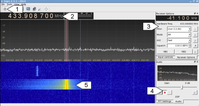 Analyzing 433 MHz radio signals from common wireless devices, such as temperature sensors and remote controls, involves understanding **On-Off Keying (OOK)** modulation. This resource details the process of capturing these signals using a Software Defined Radio (SDR) like Gqrx and then visually inspecting the captured audio data in a sound editor such as Audacity. It differentiates between **Pulse Width Modulation (PWM)** and Pulse Position Modulation (PPM) encoding schemes, illustrating how to identify and decode binary data by eye based on pulse and gap durations. The article provides a step-by-step walkthrough for decoding a wireless thermometer's data, correlating bit patterns with known temperature, humidity, and channel values. It also demonstrates decoding an RF remote control's button presses, highlighting the constant and varying parts of the transmitted packets. The content further introduces automated decoding using tools like RTL_433, explaining its capabilities in parsing various device protocols and showing how to interpret its output, including modulation type and decoded data. Specific examples include analyzing Prologue sensor protocol specifications from RTL_433's source code and noting common operating frequencies like 433.92 MHz in Europe and 915 MHz in the US.
 -
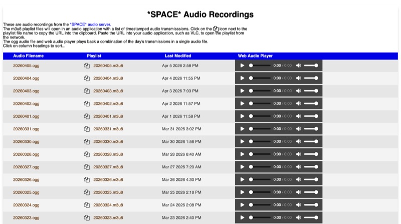 The *SPACE* Amateur Radio over Internet Protocol (RoIP) system offers public audio transmissions from NASA Mission Control and astronauts, primarily for educational purposes. This service streams NASA public media sources, including *Artemis II* and the ISS public audio channel 2 feed, which predominantly features English communications. Astronaut activities on the ISS typically occur between 0700 UTC and 19:00 UTC, with transmissions most common during early mornings USA time, alongside special events such as launches or spacewalks. Users can connect to the live stream via EchoLink to the *SPACE* conference, via IRLP to the 0100 experimental reflector, or via Allstar to node 516221. EchoLink connections utilize the GSM CODEC, while IRLP and other connections default to uncompressed or u-law CODEC. The service notes that long periods of silence are common, and NASA audio sources can be periodically unavailable or noisy. Daily recordings of these transmissions are published at space.rfnet.link/recordings/, available as .ogg audio files for direct playback or .m3u8 playlist files for network streaming in applications like VLC. Each playlist file provides a list of timestamped audio transmissions, allowing users to review specific segments of interest.
 -
 The DIY Power Meter project utilizes the _INA226_ high-side power monitoring chip, paired with an ATtiny85 microcontroller, to measure voltage, current, and power, displaying the results on a 128x32 OLED screen. The INA226 communicates via an I2C interface and is programmed with a calibration factor based on the shunt resistance and current register LSB. The project is designed to handle a maximum current of 500mA using a 0.16ohm shunt resistor, which can be adjusted to a 0.2ohm resistor, reducing the full-scale current range to 409mA with a resolution of **12.5uA**. The shunt resistor dissipates only 33mW at maximum current, making 1/4 watt resistors suitable for the setup. The PowerMeter.ino sketch configures the shunt resistance and maximum design current, automatically calculating the calibration factor. The project can be prototyped on a breadboard using an Arduino Uno, employing the Wire library for INA226 and OLED communication, and the u8g2lib library for the OLED display. For the ATtiny85 version, the Adafruit-TinyWireM and Tiny4kOLED libraries are used. The power meter is independently powered by a 3V CR2032 cell, with power switching options including manual switches or DC switched jacks. The low-side n-channel MOSFET switch configuration is tested but introduces voltage drop issues, making manual switching a more reliable option until a suitable DC switched jack is found. DXZone Technical Profile: INA226 | ATtiny85 | OLED Display | Power Meter
 -
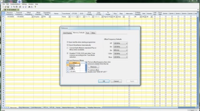 Manually programming a Yaesu FTM-100 with hundreds of channels can be very fustrating. In this article the author highlights the difficulty of entering data with small buttons and the need to look up information for each channel. To avoid this tedious process author used RT Systems software as a solution. This program simplifies programming by allowing selection based on the radio model, download of frequencies from resources like RFinder, and quick loading onto the radio. While paid unlike the free CHIRP software used previously, the author emphasizes the time saved compared to manual entry, making the cost worthwhile.
 -
 The Olivia digital mode, a **Multi-Frequency Shift Keying (MFSK)** radioteletype protocol, is specifically engineered for robust communication under difficult propagation conditions on shortwave radio bands from 3 MHz to 30 MHz. Developed by Pawel Jalocha in 2003, Olivia signals can be decoded even when the noise amplitude exceeds the digital signal by over ten times, making it highly effective for transmitting ASCII characters across noisy channels with significant fading and propagation phasing. Early on-the-air tests by Fred OH/DK4ZC and Les VK2DSG on the Europe-Australia 20-meter path demonstrated intercontinental contacts with as little as one-watt RF power under favorable conditions. Common Olivia modes are designated as X/Y, where X represents the number of tones and Y is the bandwidth in Hertz, with examples including 8/250, 16/500, and 32/1000. The resource clarifies that Olivia, unlike some other digital modes, produces a constant envelope, allowing RF power amplifiers to achieve greater conversion efficiencies and making it less prone to non-linearity. Operators are advised that **Automatic Level Control (ALC)** can be set higher than no meter movement for MFSK modulation, as long as it's not driven past its high limit, contrary to common misinformation about other digital modes. The Olivia community encourages voluntary channelization on suggested calling frequencies, such as 14.0725 MHz for 8/250, to facilitate initial contacts, especially for signals below the noise floor. The Olivia Digital DXers Club provides links to Groups.io, Facebook, and Discord for community engagement and offers details on QSO parties.