Search results
Query: coil calculation
Links: 7 | Categories: 0
-
 HamCalc is a free collection of calculators for radio amateurs include Antenna ERP calculations, Attenuators, Audio Filter design, Coil Winding, Decibels, Great Circles map and calculator, HF Filters, HF Traps, Metric conversions OP Amps QRA Locator to Latitude/Longitude, Radio Horizon calculator, Resonance Satellite orbit calculator Timer calculations (555 timer)Zener Diode calculations Download zip By G4VWL
 -
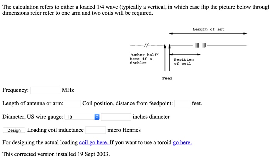 The calculation refers to either a loaded 1/4 wave or a loaded dipole,
 -
 This page lets you do calculations for single layer air cored coils using the solenoid formula
 -
 Designing and constructing portable wire antennas for HF operations, this resource explores several configurations including the _foldback dipole_ for space-constrained setups and an inductively shortened dual-band dipole for 20m and 40m. It details the calculation of inductance for shortened elements, providing a Visual Basic 6.0 program screenshot that illustrates determining coil parameters like turns and length for a **25.5 uH** inductor. The document emphasizes practical considerations such as adjusting wire lengths for optimal SWR, noting that a dual-band dipole achieved SWR below 2:1 on both 20m and 40m, with careful adjustment bringing it under 1.5:1. Further, the resource describes a half-wave antenna matched with a coaxial stub, a method often referred to as the _Fuchskreis_ in German amateur radio circles, to transform the high feedpoint impedance to 50 Ohms. This monoband solution, for a 20m application, uses a stub length of **2.98m** (0.216 lambda multiplied by coax velocity factor) and a shorted stub of approximately 48cm. The coaxial stub design is highlighted for its resilience to ground proximity, allowing it to be rolled up or laid on the ground with minimal SWR impact, making it highly suitable for portable QRP operations.
 -
 This article shares the author's experience with building antennas. After putting a large magnetic loop project on hold, they decided to try a base-loaded vertical antenna. The author explains how they chose to design a new antenna from scratch, aiming for a frequency of 7 MHz. They describe the calculations needed to find the right coil inductance and how they used 3D-printed parts for the construction. The article wraps up with results from their initial tests, showing good communication on different bands and highlighting the success of their design.
 -
 Coil64 (Coil32) is a versatile tool for calculating single-layer inductance coils used in various electronics, such as matching circuits and amplifiers. The online calculator enables users to estimate the number of turns, winding dimensions, and select the appropriate wire type for home-brewed RF inductors. It employs Bob Weaver's equation, factoring in wire corrections, and allows for the calculation of Q-factor and self-capacitance. Coil64 is compatible across multiple platforms, including Windows, Linux, Mac-OS, and Android.
 -
 Demonstrates the design and modeling of a **160m** vertical antenna, dubbed the "WindoVert," specifically for urban amateur radio operators with limited space. The resource covers the theoretical underpinnings of antenna height and radiation patterns, using EZNEC software to analyze current distribution and 3D radiation patterns for various configurations, including a Marconi-style "T" antenna. It details the integration of existing antenna components, such as a Carolina Windom balun and line isolator, into the new vertical setup, and the practical measurement of feedpoint impedance using an antenna analyzer. The article further explores the challenges of achieving low-angle radiation on Top Band, emphasizing the critical role of radial systems and mitigating ground loss. Author VE1ZAC presents EZNEC models illustrating the impact of lumped components and discusses the practical considerations of resonant frequency adjustment and impedance matching for **QRP** operation. The text details the calculation of required loading coil inductance and capacitance, and shares field results, including successful DX contacts on 160m and unexpected excellent performance on 30m.