Search results
Query: connector guide
Links: 20 | Categories: 1
-
 This resource provides a detailed guide on constructing a J-pole antenna specifically for the 2 meter band, which is popular among amateur radio operators. The article outlines the materials needed, including various sizes of aluminum pipes and PVC, as well as the tools required for assembly. It emphasizes the simplicity and effectiveness of the J-pole design, making it an ideal choice for newcomers to amateur radio. The instructions are straightforward, allowing users to build the antenna in less than an hour, and include tips for tuning the antenna for optimal performance. In addition to the construction details, the resource includes practical advice on the assembly process, such as how to cut and join the pipes, as well as how to mount the SO239 connector. The author shares personal experiences and insights on achieving a low standing wave ratio (S.W.R.) and suggests modifications for creating bi-band or tri-band J-pole antennas. This comprehensive guide is enriched with photographs that illustrate the construction steps, making it easier for users to follow along and successfully build their own J-pole antenna.
 -
 This guide provides step-by-step instructions for constructing a tin can waveguide antenna, commonly known as a cantenna, for enhancing WiFi signal range. The project is budget-friendly, costing under $5, and utilizes easily accessible materials like a food can and basic electronic components. The design is suitable for 802.11b and 802.11g wireless networks, operating within the 2.4 GHz frequency range. To start, gather the necessary parts including an N-Female chassis mount connector, nuts, bolts, and a suitable can. The assembly process involves drilling holes in the can for the connector and mounting the probe. The guide emphasizes the importance of can dimensions and placement for optimal performance, encouraging experimentation for best results. This project is ideal for amateur radio operators and DIY enthusiasts looking to improve their wireless connectivity without significant investment. Safety precautions are advised, as the author does not hold electrical engineering credentials. Users are encouraged to take responsibility for their equipment and ensure proper assembly. With this simple yet effective antenna, users can extend their WiFi coverage and enjoy enhanced connectivity.
 -
 A very beginner's guide to coax cables. Characteristics, detailed comparison of typical coaxial cables, commonly used connectors, and a few words about SWR.
 -
 This online guide details the microphone pinout for the Kenwood TR-7950 transceiver, specifically addressing the wiring configuration for a dynamic mobile microphone with a **500 Ohm** impedance. It provides a pin-by-pin breakdown for the 6-pin microphone connector, identifying the function of each active pin. The resource specifies that Pin #1 is for the microphone audio (white wire), Pin #2 controls the _PTT_ (black wire), Pin #3 activates the memory down function (blue wire), and Pin #4 controls the memory up function (red wire). Pin #6 is designated as the ground connection, while Pin #5 remains unused in this configuration. The document focuses on the physical wiring necessary to restore microphone functionality to the Kenwood TR-7950, a transceiver capable of **45 watts** output on the _2m band_. It directly addresses the technical challenge of re-establishing correct electrical connections after microphone wires have been disconnected from the connector. The information facilitates proper microphone operation for simplex QSOs and other voice communications. DXZone Focus: Online Guide | Microphone Pinout | Kenwood TR-7950 | PTT Wiring
 -
 This online project guide details the construction of a homebrew boom microphone system. It details the assembly of a microphone shell from a 3/4" PVC pipe section and an end cap, requiring a drilled hole for a snug fit of the electret or condenser mic element. The internal wiring schematic specifies a **2.2 K** resistor and a **47 uF** polar capacitor for signal conditioning, with a circuit diagram provided for integration with IC-706 series transceivers. The guide outlines the use of CAT-5 cable for internal connections, incorporating strain relief at the rear of the mic shell, and an inline 3.5 mm jack to facilitate an external _PTT_ line, designed for a foot-mounted switch. Further construction involves fabricating a microphone shock mount from a 2-inch PVC connector, detailing the creation of four "fingers" and the insertion of screw-eyes for attaching elastic bands, which are twisted 180 degrees for tensioning and vibration isolation. A foam wind screen is also incorporated into the microphone assembly, secured with adhesive. The boom arm itself is repurposed from an articulated architect lamp, with the original lamp assembly converted into a **60 watt** resistive load for testing power sources. Microphone cabling is secured to the boom arm using wire ties, ensuring sufficient slack at hinge points to maintain articulation. The boom base is mounted to a bookshelf, requiring specific positioning to achieve proper microphone placement in front of the operator. Performance evaluation of the microphone system is conducted through on-air audio signal reports from other amateur radio operators. DXZone Focus: Online Project Guide | Boom Microphone Construction | Electret Mic Element | PTT Line
 -
 Constructing a digital interface for the Elecraft K2 transceiver, this resource details the "Fat Wire" design by WG4S. It demonstrates how to integrate a sound card for digital modes, outlining specific connections to the K2's microphone jack and internal audio path. The author shares practical insights from his build, including the use of _RG-62_ coax for its flexible braid and the strategic placement of components like the 2.2K resistor and _2N2222_ transistor. The guide provides a breakdown of the interface's internal wiring, specifying connections for AF In (pin 1), AF Out (pin 5), PTT (pin 2), and Ground (pin 7) on the K2's microphone connector. It also covers the external connections to a laptop's headphone and line-in jacks, along with a DB-9 connector for PTT control via _DTR_ or RTS lines. The author notes that his laptop's headphone output level was sufficient for the K2, negating the need for an attenuator. Reflecting on the design, the author, Dan WG4S, acknowledges a later suggestion to house the components directly within the DB-9 shell for a more compact build. This iterative feedback highlights the ongoing evolution of DIY ham radio projects and the community's collaborative spirit in refining designs.
 -
 Anderson Powerpole connectors are becoming the standard for Raynet ARES and RACES groups as well as many Ham radio shacks round the world. This recourses page will give you a guide to Anderson Powerpole connectors in the radio shack.
 -
 Cmpter Electronics specializes in the design and manufacturing of RF coaxial connectors, RF adapters, and RF cable assemblies, serving diverse applications across datacom/telecom, automotive, instrumentation, aerospace, and defense sectors. Their product line includes RF coaxial terminations, attenuators, and waveguide to coax adapters, catering to specific needs in radio frequency systems. The company also offers precision adapters and connectors, alongside glass beads and test cable assemblies, indicating a focus on high-quality components for demanding RF environments. Their resource center provides valuable information, including an "RF Made Simple" section and a product catalog for download, which assists engineers and technicians in selecting appropriate components. The product named system helps in identifying specific parts, streamlining the procurement process for complex RF solutions. With a comprehensive range of RF coaxial cables and related tools, Cmpter Electronics positions itself as a key supplier for critical infrastructure requiring reliable signal integrity. Their offerings support a broad spectrum of RF applications, from basic connectivity to advanced test setups.
 -
 Coaxial cable stripping for PL-259 connectors requires precise measurements to ensure optimal RF performance and mechanical integrity. For RG-8X, the outer jacket is stripped 1/2 inch, the braid 5/16 inch, and the dielectric 1/8 inch, leaving the center conductor exposed. RG-58 preparation involves a 1/2 inch jacket strip, 1/4 inch braid strip, and 1/8 inch dielectric strip. These specific dimensions facilitate proper soldering and crimping, minimizing impedance discontinuities at the connector interface. Different coaxial cable types, such as RG-8 and RG-213, necessitate varied stripping lengths due to their construction. The _PL-259_ connector, a common UHF type, relies on these exact preparations for a secure fit and low-loss connection. Incorrect stripping can lead to high SWR, RF leakage, and mechanical failure, impacting overall station efficiency. The guide details these critical dimensions for several popular coax cables. Using a dedicated _coax stripper_ tool or precise measurements with a utility knife improves consistency.
 -
 Demonstrates MegaPhase's extensive product line of RF and microwave coaxial cable assemblies and components, engineered for demanding applications up to 110 GHz. Key offerings include _Test & Measurement Cables_ with superior phase and amplitude stability, _RF & Microwave Cables_ utilizing _GrooveTube®_ technology for high power systems, and a range of RF components like directional couplers and power dividers. The site details specific cable types such as _Alumibend™_ for space-qualified, ultra-light applications through 90 GHz, and armored cables designed for rigorous environments up to 50 GHz, emphasizing their robust mechanical strength and measurement repeatability. The resource highlights applications across diverse sectors, including space programs like the _Hayabusa_ mission, global security (C5ISR), military airborne systems (MIL-T-81490), telecom, and automated testing. It also provides technical insights through "How To" guides on measuring amplitude/phase stability vs. flexure and proper connector cleaning. The company's commitment to quality is underscored by its rigorous testing protocols and a strong warranty, ensuring reliable operation in critical systems.
 -
 The Tri-pole antenna, a clever modification of a standard dipole, allows for dual-band operation by integrating a third element. This design effectively shortens the overall dipole length by 10 to 20 percent, simplifying antenna rotation and offering a compact footprint. KK4OBI's article delves into the operational principles, using a 6 and 10-meter Tri-pole as a primary example, and provides comprehensive instructions for constructing any Tri-pole antenna within the 6 to 15-meter range. Key to the Tri-pole's performance is its off-center feed, necessitating a common mode choke at the feed point for optimal tuning and reduced noise. The author outlines a methodical approach to determining element dimensions, starting with a vertical element frequency calculated as 0.47 times the sum of the desired upper and lower band frequencies. This calculation, along with K-values derived from trend lines, guides the initial lengths for the horizontal arms, demonstrating how a 10m-6m Tri-pole can achieve a total horizontal length 78% shorter than a conventional 10-meter dipole. Tuning and balancing are critical, with the article detailing adjustments to arm lengths and the vertical element to achieve balanced SWR values, as validated through 4NEC2 simulations. Radiation patterns are analyzed at various elevations, showing gains around 5.7 dBi and favorable take-off angles for DX contacts. Construction details specify aluminum tubing dimensions, U-bolts, and an SO-239 connector, emphasizing the importance of a ferrite-based choke for wideband operation.
 -
 Building an End-Fed Half-Wave (EFHW) antenna from a kit, as detailed by Frank Bontenbal, PA2DKW, with process photos by Bob Inderbitzen, NQ1R, offers a practical approach for hams. This specific kit, a collaboration between ARRL and HF Kits, targets 10, 15, 20, and 40 meters, making it a versatile option for HF operations. Unlike a center-fed dipole, the EFHW is a half-wavelength antenna fed at one end, which simplifies deployment, particularly for portable use. The construction guide meticulously outlines the assembly of the 49:1 impedance matching network, crucial for transforming the antenna's high impedance (around 2,500 Ohms) to a transceiver-friendly 50 Ohms. Steps include preparing the enclosure by drilling holes for the coaxial connector and antenna connections, followed by the precise winding of enameled copper wire onto a toroid to create the transformer. The guide emphasizes careful insulation removal and soldering for reliable connections. Final assembly involves integrating a 100 pF capacitor for higher band compensation, soldering the transformer's primary and secondary sides, and conducting SWR tests with a 2K7 resistor or a half-wavelength wire. The document also provides examples of wire lengths for different bands, such as 16 feet for 10 meters or 66 feet for 40 meters, demonstrating the transformer's adaptability for various half-wavelength configurations.
 -
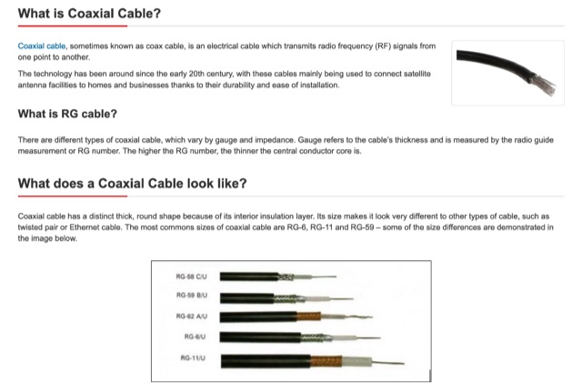 An technical page on coaxial cables that describes what coax cables are, how do coax cables works, what are RG cables and difference with several coax cable types, what they are used for, connector types and cable sizes
 -
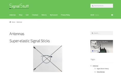 Signal Stuff operates as an online retail outlet specializing in amateur radio antennas and related accessories, with a core mission to financially support educational platforms like HamStudy.org and ExamTools.org. The product line prominently features their Super-Elastic Signal Stick™ antennas, available with SMA-F, SMA-M, and BNC connectors, designed for various handheld transceivers including Baofeng, Icom, Yaesu, and Kenwood models. The site details product specifications, pricing, and a lifetime warranty for the Signal Stick™ antennas, emphasizing their role in funding free ham radio licensing study guides and exam administration software. Proceeds from antenna sales directly contribute to the development and maintenance of HamStudy.org, a free online resource for amateur radio license preparation, and ExamTools.org, software utilized by Volunteer Examiner (VE) teams for efficient exam administration. The site also promotes HamBook.org, a free series of comprehensive study guides, which integrates with the HamStudy app and website through links and QR codes for an adaptive learning experience. This business model links product sales to community support, providing essential tools for aspiring and upgrading amateur radio operators.
 -
 Learn how to build a portable receiving antenna for the 160 meter band. This guide provides detailed instructions on constructing a loop antenna using a coaxial cable RG-316 with SMA connectors. The antenna weighs 1.7 kg and has dimensions of 2m in height and 1.892m in width. The wooden frame consists of four 0.945m long pieces and two 1m long pieces. Perfect for hams looking to enhance their 160m band reception during travel or portable operations.
 -
 Ferrite E-cores offer a practical solution for constructing baluns, especially when connectors are already mounted on cables. These cores, commonly used in mass-produced pulse transformers, allow for multiple turns without dismounting connectors, making them ideal for control and power supply cables. The material of E-cores is generally suitable for common mode baluns up to 15 MHz, providing a cost-effective option for amateur radio operators. E-cores can often be sourced from old switch-mode power supplies, adding to their appeal for those looking to utilize existing resources. A notable example involves a balun on a USB cable using a Ferroxcube E 32x16x9, 3F3 core with four turns, secured by three cable ties. This setup demonstrates the ease of construction and stability achievable with E-cores. Another example features a balun with eight turns of shielded cable with RCA connectors on the same core, achieving 140 uH inductance at low frequencies. The impedance plot for this configuration is measured between the shield ends, illustrating the effectiveness of E-cores in practical applications. The article includes detailed figures and descriptions, providing valuable insights into the construction and application of baluns using ferrite E-cores. These examples serve as a guide for amateur radio enthusiasts looking to enhance their setups with cost-effective and efficient solutions.
 -
 The resource details the construction of a 433 MHz LoRa APRS iGate and a tracker, both built around _TTGO T-Beam v1.1_ microcontroller boards. Each board integrates an OLED screen, WiFi, GPS, and an SMA antenna connector, powered by an 18650 3.7 V lithium-ion battery or microUSB. The iGate operates on 433.775 MHz, with its status verifiable on aprs.fi, demonstrating practical implementation of LoRa-based APRS solutions. The methodology involves programming the modules using Visual Studio Code with the PlatformIO plugin. This process loads the necessary firmware and a JSON configuration file, which includes the operator's callsign and WiFi credentials for the iGate. The guide emphasizes the ease of programming and provides specific steps for configuration. Initial testing of the iGate and tracker, including smart beaconing configuration, is documented. The low power output of approximately 200 mW from the LoRa board's transmitter is noted, with suggestions for range extension through improved antennas or RF amplification. The author, N4MI, plans to deploy a higher-gain 70cm antenna for the iGate.
 -
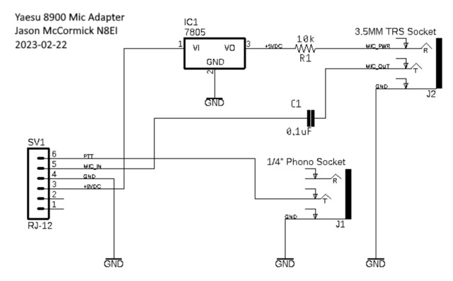 Explore the process of creating a custom adapter for the Yaesu FT-8900 radio with a non-standard mic port. The article guides users through understanding the reversed pin-out of the RJ-12 connector on the 8900, providing a detailed circuit for adapting the voltage for electret-based mics. With a list of required parts and construction tips, this DIY project ensures seamless compatibility with standard electric headset mics.
 -
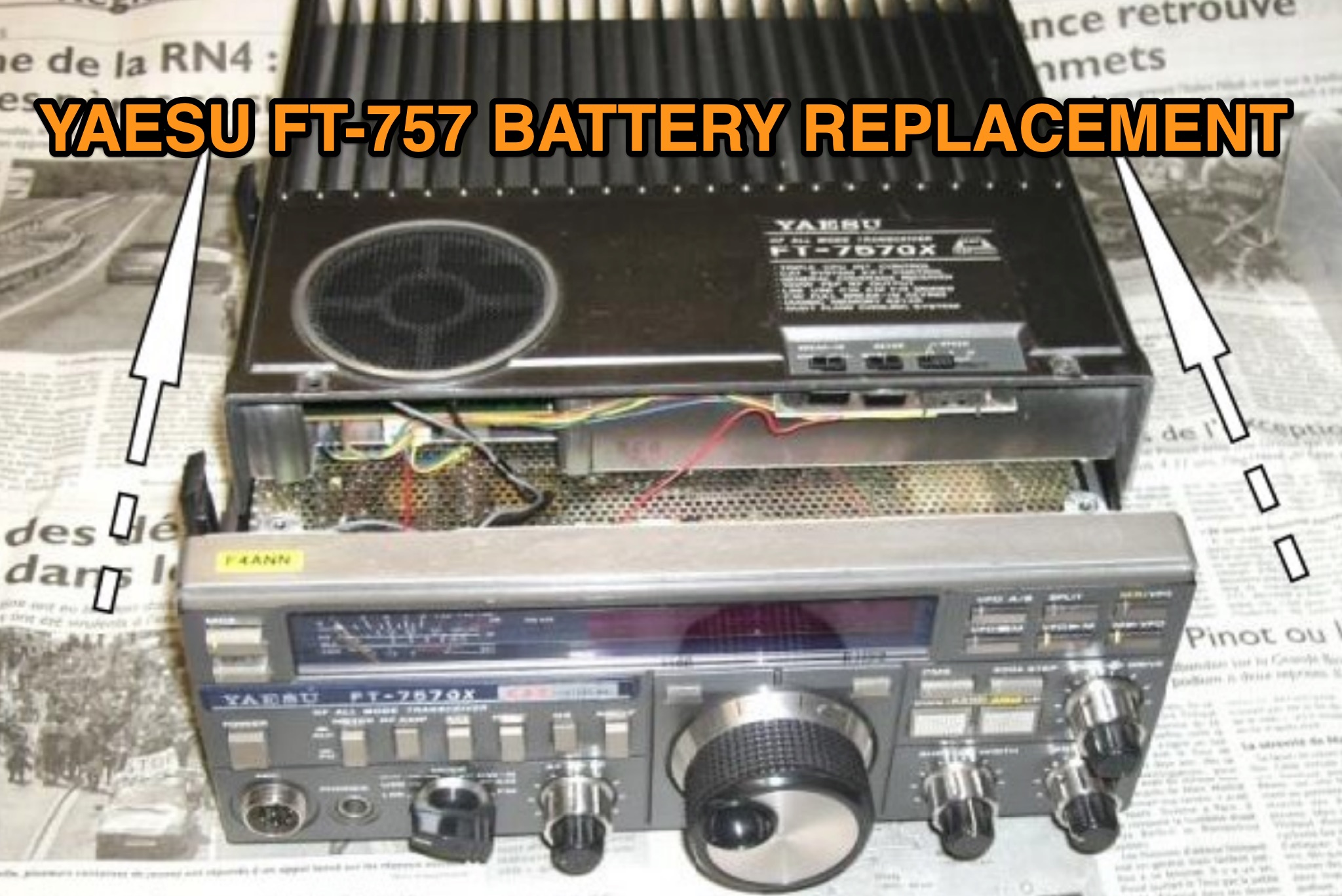 This guide by F4ANN (2014) explains replacing the backup battery in a YAESU FT-757 GX when stored frequencies reset on power-up. The original CR-1/3N lithium cell (3V, 160 mA) can be substituted with a CR2032 (170 mA), which is cheaper, widely available, and easier to replace. The process involves opening the transceiver, carefully desoldering the old battery from the PCB, and wiring in a holder for the CR2032. Extra care is required with screws, connectors, and soldering. The author also replaced backlights and serviced the cooling fan. Future battery replacements are simplified to four screws.
 -
 Twenty 1-watt carbon film resistors are configured in parallel to construct a 50-ohm **dummy load** for amateur radio applications. The design incorporates a heatsink for thermal dissipation and an **SO-239 connector** for RF input, making it suitable for QRP operations. This budget-friendly project details component selection, soldering techniques, and mounting procedures, achieving a continuous power rating of 10 watts and intermittent handling of up to 100 watts across HF and VHF frequency ranges. The resource provides a step-by-step guide for assembly. This construction offers an economical solution for essential shack tasks such as antenna tuning, transmitter testing, and SWR meter calibration without radiating an RF signal. The utilization of readily available components significantly reduces the overall build cost compared to commercial alternatives, providing radio amateurs with a functional and reliable test accessory. While specific VSWR measurements are not provided, the design prioritizes practical utility for low-power transceiver diagnostics and general RF experimentation.