Search results
Query: folding antenna
Links: 6 | Categories: 0
-
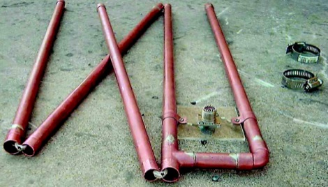 Also known as the Backpacker's Delight Antenna. This Folding J Pole Antenna is the original design of Mike Heiler KA0ZLG and was featured on the Front Cover of the March 2005 QST Magazine.
-
 The K5OE 2-meter vertical mobile antenna design, detailed in this resource, employs a 3/8-wavelength vertical section complemented by four shortened radials, forming an off-center-fed vertical dipole. This configuration creates a self-contained lower half, enhancing efficiency compared to traditional 1/4-wave monopoles relying on vehicle bodies for a ground plane. The article specifies construction using PVC components, 10-gauge insulated wire for elements, and provides precise dimensions in both inches and centimeters for the 25-3/16" (64 cm) vertical and 7-3/16" (20 cm) radials. Performance data indicates an honest 3 dBi of gain at 6 feet elevation (2 dBi free-space), with a pattern favoring the horizon, suitable for Low Earth Orbit (LEO) satellite communications. At 20 feet high, the same antenna exhibits almost 6 dBi of gain, with a nominal 50 Ohm feedpoint impedance at 146.850 MHz. Tuning instructions involve trimming element lengths, with the author achieving a 1.2:1 SWR by pruning the mast to 24-3/4" and radials to 7". The resource highlights the antenna's effectiveness for mobile LEO satellite uplinks, particularly at low elevations, and its suitability for fixed, mobile, or portable operations. The flexible wire elements allow for easy folding, making it a practical choice for backpacking. The original design by K5OE was previously hosted on aol.com.
-
 The half wave dipole antenna is a simple and practical antenna model that consists of a half wavelength long centre fed conductor.
-
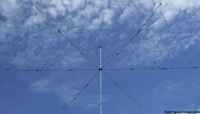 Ultra portable and lightweight folding beam antennas based on G3TXQ design
-
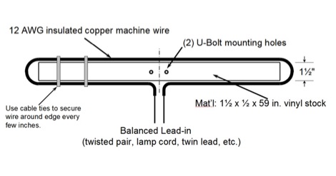 The folded dipole antenna, often claimed to offer increased bandwidth and a close match to 300-ohm line, is examined in detail. This analysis challenges several prevalent myths, including the assertion that a folded dipole inherently provides wider bandwidth than a thin wire dipole on a single band. The article clarifies that any bandwidth improvement primarily results from the antenna's increased thickness, not from stub effects, folding, or higher feedline impedance. It also addresses the misconception that a folded dipole is an effective multiband antenna, explaining its poor performance on even harmonics where it presents a near dead short. Further discussion refutes the idea that SWR variations are less with changes in antenna length or frequency compared to a regular coax-fed dipole. The resource demonstrates that SWR variations are essentially similar, with folded dipole impedance ranging from approximately 200 to 300 ohms, leading to comparable SWR levels. It also corrects the belief that balanced line feed inherently offers low loss at high SWR, emphasizing that loss is primarily related to the physical characteristics of the transmission line rather than its balanced nature. Modeling results are presented, comparing a folded dipole with 300-ohm and 200-ohm feed lines against regular dipoles fed with 50-ohm and 75-ohm coaxial cable, and a single #14 insulated wire dipole. The data shows negligible differences in 2:1 VSWR bandwidth between folded and regular dipole systems when effective wire diameter is constant, reinforcing the argument that thickness is the dominant factor in bandwidth.
-
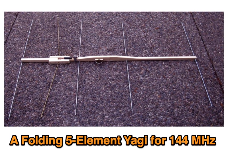 Presents the design and construction of a folding 5-element Yagi antenna specifically engineered for 144 MHz portable operation, particularly for VHF contest Rover categories. It details element dimensions, boom construction using ¾-inch pine, and a folding mechanism that reduces the 52-inch boom to 26 inches for transport. The document provides a table with precise element distances and lengths, including a 2.4 mm length correction for solid parasitic elements, and specifies the use of 3/16-inch solid aluminum for parasitic elements and brass tubing for the driven element. It also covers the bent dipole driven element design for impedance matching, balun implementation with Type 31 ferrite beads for common mode current suppression, and weatherproofing for the feed point. The resource includes predicted performance data from 4NEC2 modeling, showing SWR and return loss characteristics, as well as gain and front-to-back ratios at various frequencies across the 2-meter band. It reports a measured SWR of 1.2:1 at 144.2 MHz and 1.5:1 at 147 MHz, corrected for 25 feet of RG-8/M coaxial cable loss. The design offers approximately 1.5 dB more gain than a previous 4-element design, maintaining a decent SWR up to 147 MHz, and was successfully deployed in a winning June 2016 ARRL VHF Contest Rover entry.