Search results
Query: interference detection
Links: 4 | Categories: 0
-
 A PIC16F876 microprocessor-based digital SWR/WATTmeter project provides automatic operation across the 1.8 to 60 MHz frequency range. This design displays both SWR and P.E.P. power values, incorporating a bar graph on the second LCD line for instantaneous power tracking. The directional coupler utilizes a single-wire coil on a ferrite FT50-43 toroid, balanced with a 60 pF trimmer, and employs 1N5711 Schottky diodes for detection, ensuring linearity and a power range of 5 to 120 W. The software, developed by IW3EGT, compensates for diode voltage drop for precise readings, updating power every two seconds for stable display of modulated carriers, while the bar graph updates ten times per second for near real-time feedback. Calibration involves two phases: adjusting the directional coupler for minimum SWR on a 50-ohm dummy load at 28 MHz, and calibrating the microprocessor system by inputting a calculated power value (Power (Watt) = (Vout + 0.5)^2 / 100) at 14-21 MHz. The project includes PCB layouts for both the directional coupler (two-layer copper board) and the PIC module (single-sided), with specific instructions for component placement and shielding to prevent RF interference. The design allows for modification of power reading capability by varying the number of turns in the coupler coil, catering to different power levels.
 -
 The _Letter Post Regulations_ article RL 128 defines specific dimensional requirements for address placement on envelopes, crucial for efficient postal processing. The addressee's address area must be positioned at least **15 mm** from the right and bottom edges, and at least **40 mm** (with a 2 mm tolerance) from the top edge, extending no more than 140 mm from the right-hand edge. These precise measurements ensure rapid optical reading and facilitate manual sorting and delivery by postal services. Adherence to these Universal Postal Union (UPU) standards prevents interference with indexing, coding, and address detection areas, which must remain blank. While individual countries may adapt these values, they must maintain a minimum address area width of 74 mm. Proper placement avoids extraneous markings to the right, below, or within a 15 mm wide area to the left of the address, extending from the first line to the bottom edge, and a 15 mm high by 140 mm long area from the bottom-right corner.
 -
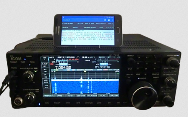 MorseExpert 1.15 decodes Morse Code audio to text, leveraging algorithms from CW Skimmer for optimal performance on weak, fading signals amidst interference on amateur radio bands. It processes audio from the device's built-in microphone or an external radio receiver via cable, optionally highlighting Ham callsigns and keywords. The application features a waterfall display with a bandwidth of 200-1200 Hz, decodes frequencies between 300-1100 Hz, and supports keying speeds from 12-45 WPM with automatic CW pitch detection. Recent updates include support for Android 15, edge-to-edge mode, improved stability, and a pause decoding button. A premium version offers an ad-free experience and user-selected text colors. Users can switch between General Text mode and Ham Radio QSO mode, which enhances word segmentation and highlights callsigns. The app also includes a frequency lock mode, text selection capabilities for copying, sharing, or saving decoded text, and provides guidance on reducing acoustic echo and constructing an audio attenuator for optimal radio interfacing.
 -
 Understanding how radio frequency interference (RFI) is coupled into equipment and subsequently detected is crucial for amateur radio operators. This guide delves into the fundamental mechanisms of RFI, particularly focusing on detection at semiconductor junctions and the unintended antenna action of system wiring. It explains that most RFI detection follows a square law, meaning a 6 dB reduction in RF signal can result in a 12 dB drop in detected audio, offering a practical approach to mitigation. The resource also clarifies the concept of common mode versus differential mode signals, detailing how cable imperfections can convert common mode antenna current into differential signals. It addresses the critical "Pin 1 Problem" in audio interfacing, a common design flaw where cable shields connect to the circuit board instead of the shielding enclosure, leading to significant RFI issues. Practical solutions, such as proper shielding, using twisted-pair cables, and strategic bonding of equipment, are discussed to effectively reduce or eliminate RFI. The guide emphasizes the importance of proper filtering and the often-misunderstood concept of "ground" in electrical systems, distinguishing between earth ground, equipment ground, and circuit common. It provides insights into minimizing loop area in wiring to reduce inductively coupled noise and antenna action, drawing on the author's extensive engineering background and ham radio experience.