Search results
Query: measure tape
Links: 12 | Categories: 0
-
 A rotary trapped-dipole for 17 and 20 meters, as described by IZ7ATH, presents a practical solution for multi-band HF operation. The author, Talino, recounts his experience building this antenna for IK7ZCQ, detailing the evolution from an initial concept involving a grounded-driven element and gamma-match to a direct-fed, non-grounded design. His pragmatic approach, adapting available materials, is evident throughout the construction narrative, particularly with the use of eight tapered aluminum pipes for the driven element. Construction specifics include precise measurements for the aluminum tubing, with diameters ranging from 30 mm down to 16 mm, and a critical note on reducing tip thickness for weight optimization. The _traps_, initially a concern, are fabricated using 8 turns of RG58 coax on a 27 mm support, tuned to resonate at 18.1 MHz using a dip-meter. Talino emphasizes sealing the traps with RF glue and PVC tape to prevent water ingress, a crucial step for longevity. Field test results, conducted on a 10-meter pole in a clear garden environment, showed an SWR of 1.2:1 on 17 meters and 1.5:1 at 14.200 MHz. While SWR varied slightly when installed at Mario's QTH due to nearby objects, the antenna's performance remained commendable. The final half-dipole length is 46 cm for the 18 MHz tips, and the total weight is under 6 kg, with potential for further reduction.
 -
 Examines the operational principles of loading inductors within **mobile HF antennas**, clarifying their role in canceling capacitive reactance rather than physically replacing missing antenna length. It meticulously details how current distribution is influenced by stray capacitance and termination impedance, rather than the physical length of wire within the coil itself. The resource provides a deep dive into the behavior of inductors, emphasizing that a loading coil functions identically to any other inductor in an electronic circuit, with its characteristics determined by its design and surrounding impedances. This article specifically addresses common misconceptions, such as the idea that loading coil current is reduced by standing waves or that coils introduce a significant electrical-degree phase delay related to conductor length. It explains that magnetic flux coupling within the coil causes charges to move at light speed, resulting in minimal time delay across the inductor, especially in well-designed, compact units. The author, W8JI, presents both theoretical explanations and empirical measurements to support these points, including data from various antenna configurations. Furthermore, the content clarifies the distinction between voltage-current phase shift within an inductor and actual current time delay through it, using **SPICE models** and real-world observations. It highlights that large current taper in a loading coil often indicates poor antenna or tank circuit layout, rather than an inherent property of the inductor itself. The discussion also touches on the impact of stray capacitance on inductor Q and bandwidth, offering insights into optimal form factors for different applications.
 -
 JJ0DRC's HF multi-band delta loop antenna project, initially conceived during the waning peak of Cycle 23, addresses the common challenge of achieving effective DX operation from a small residential lot in Japan. Dissatisfied with a ground plane antenna's performance in SSB pile-ups, the author sought a beam-like solution without a tower, drawing inspiration from a JJ1VKL article in CQ Ham Radio Sep. 2000. The antenna, constructed in October 2000, employs two 7.2-meter fishing rods (37% carbon fiber, reinforced with cyano-acrylate glue and aluminum tape) and 1mm enameled wire, fed by an Icom AH-4 external antenna tuner. While the exact beam pattern remains unmeasured, JJ0DRC observed a significantly higher callback rate compared to dipole antennas, particularly on higher bands. The system's circumference length of 15-20m is crucial for maintaining a good beam pattern across HF bands, though performance on lower bands like 80m, 40m, and 30m becomes less directional as the length deviates from a full wavelength. Ongoing maintenance addressed degradation issues, including aluminum tape cracking and wire breakage at connection points due to strong winds (often exceeding 10-15m/s in winter). The author reinforced rod connections with IRECTOR PIPE SYSTEM components and INSU-ROCK ties, and improved wire attachment methods using Cremona rope and epoxy bond to enhance durability.
 -
-
 One point eight MHz to 30 MHz is the operational bandwidth for this 4:1 Ruthroff voltage balun, designed to interface an unbalanced T-Match network with a balanced antenna system. The project details the construction using a _T200-2_ powdered iron toroid core, tightly wrapped in PVC electrical tape for insulation, and wound with 17 double bifilar turns of 1.25mm enamelled copper wire. This outboard balun offers flexibility, allowing hams to trial various baluns based on antenna system and impedance characteristics, rather than integrating it directly into the tuner. The resource includes a schematic of the balun, a wiring diagram showing winding connections, and a table suggesting alternative toroid cores like the T80-2 or T400-2 with corresponding winding counts. Component sourcing is straightforward, listing items such as the _Amidon_ T-200-2 core, SO-239 connector, and a sealed polycarbonate enclosure from Jaycar. Performance evaluation was conducted using an _AIM 4170C_ antenna analyser, demonstrating efficient 1:4 voltage transformation across the specified HF spectrum. Further efficiency tests involved measuring RF power loss at various frequencies, revealing minimal loss—less than 0.7 dB from 3.6 MHz to 30 MHz, and only 2.0 dB at 1.8 MHz. These measurements, performed under ideal 50-ohm conditions, confirm the balun's effectiveness as a low-loss interface for multi-band antenna systems. The page also links to several other balun and unun projects, including 1:1 current and voltage baluns, and 9:1 voltage ununs, providing a broader context for impedance matching solutions.
 -
 This resource details the construction of a Moxon rectangle antenna, a two-element wire beam, drawing inspiration from a _QST_ article by Allen Baker, KG4JJH, and a project group led by KD6WD. It outlines the use of _AC6LA_ software for critical measurements (A-E) to design the antenna for specific bands like 17 meters, emphasizing the simplicity of adjusting frequency and wire size. The guide covers material selection for spreaders, such as telescoping fiberglass fishing poles, and various hub constructions, including aluminum tubing and PVC joints, with accompanying images. The author shares practical insights from building multiple Moxons for 10, 15, 17, and 20 meters, noting consistent 1:1 SWR at design frequencies and broadbanded performance. It describes the feedpoint assembly using a 1:1 Yagi current balun and wire nuts for robust, adjustable connections. The resource also discusses element insulators made from Lucite strips and attachment methods to spreaders using plastic wire ties and duct tape, ensuring precise element spacing. Performance observations include significant signal improvements (4-5 S units) over quad loops and a unique "DX-Vane" effect where the suspended antenna self-aligns with the strongest DX signal. The author also recounts an unsuccessful attempt at a dual-band 17/20 meter Moxon, concluding that the Moxon is inherently a monoband antenna, supported by _EZNEC_ plots for a 17-meter design.
 -
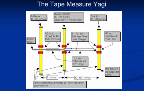 A presentation of the Yagi Antennas, and other interesting tid-bits by Brian Mileshosky. The document provides an in-depth exploration of the Yagi-Uda antenna, detailing its historical development, design principles, and performance characteristics. Originally described in the 1920s, the Yagi antenna features a driven element and parasitic elements, including reflectors and directors, which collectively determine its behavior. The document highlights how element lengths, diameters, and spacing influence gain, impedance, and directivity. It also discusses the antenna's reciprocal nature and presents data on typical gain values for various element configurations. Additionally, the text covers practical considerations, such as the construction of a "Tape Measure Yagi" for amateur use, and touches on related antenna types like dipoles and their application in Near Vertical Incident Skywave (NVIS) communication.
 -
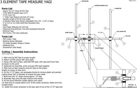
 A 7 dB directional gain is reported for this portable VHF Yagi antenna design, which utilizes cut metal tape measure sections for its elements. The resource details the construction process for a 2-meter band antenna, emphasizing its ease of build and portability. It specifically mentions the design's suitability for radio direction finding (RDF), fox hunting, and communication with satellites and the International Space Station (ISS), highlighting its practical applications for amateur radio operators. The construction cost is estimated at under $20, with potential for even lower expense if salvaged materials like old tape measures and PVC pipes are used. The article references _Joe Leggio's_ (WB2HOL) original design, noting specific alterations made by the author. It also compares this design to other DIY Yagi antennas, including _FN64's_ 2-meter band and _manuka's_ 70-cm band tape measure Yagis, underscoring its unique combination of simplicity, portability, and effective performance with a 1:1 SWR achievable on the 2-meter band.
 -
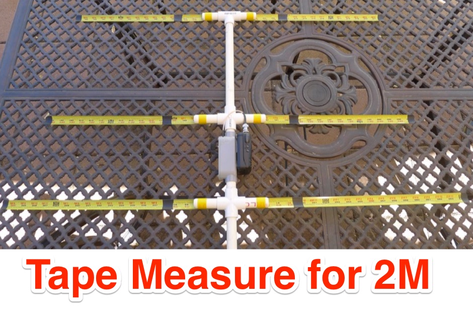 A Tape Measure Beam Antenna for Radio Direction Finding based on WB2HOL design.
 -
 This resource, despite its title, does not provide information relevant to amateur radio operations or the W1BD Central Vermont Amateur Radio Club. Instead, the content focuses on commercial topics such as vinyl lettering, business signage, and brand recognition strategies. It details the application of _transfer tape_ for graphics, the importance of pre-masking in vinyl cutting, and the use of squeegees for smooth decal application. The site also discusses various types of business signs, including monument signs and awning signs, highlighting their role in attracting customers and establishing brand presence. Further sections delve into home maintenance tasks like gutter cleaning, offering advice on using power washers and the importance of safety measures when working on ladders. The content also explores strategies for building brand recognition and customer loyalty, emphasizing consistent marketing efforts and excellent customer service. It touches upon the use of custom-printed bags and digital displays, such as LED signs, for enhanced visibility and engagement. The site's articles include practical tips for kitchen renovations, such as upgrading cabinet hardware, adding pendant lighting, and repainting cabinets to achieve a fresh look without significant expense. The content is entirely unrelated to amateur radio activities, club information, or technical aspects of radio communication.
 -
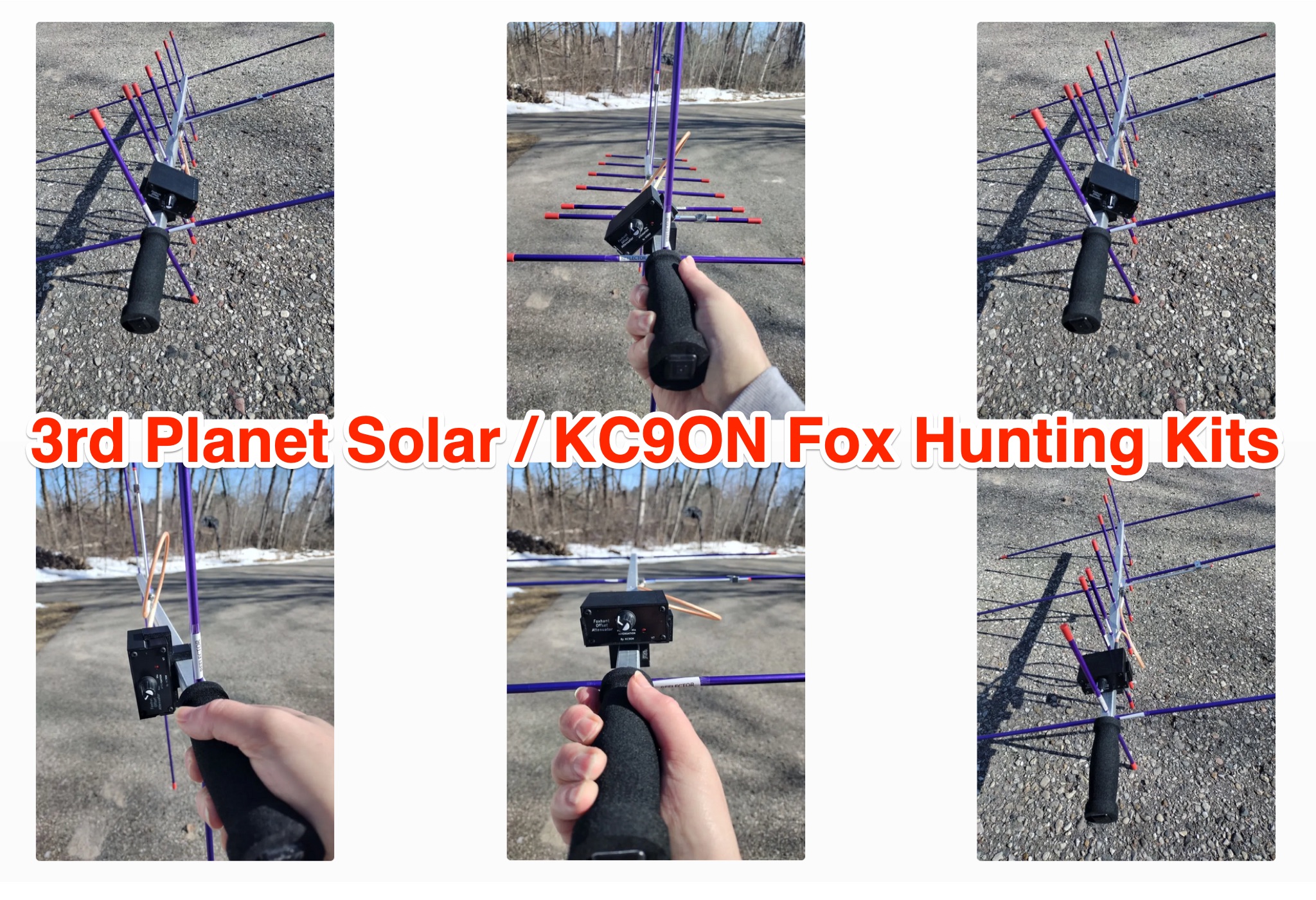 Explore the world of fox hunting with the Fox Hunt V7 Kits and Assembled Units. Learn about the different antennas used for fox hunting, such as the tape measure beam with an offset attenuator. Discover how to make your own WB2HOL beam antenna using PVC pipe, T's, and a tape measure. Find out how the offset attenuator works and how it can help you track down jammers and interference. Whether you're a seasoned fox hunter or just starting out, this page offers valuable insights and tips for improving your hunting skills.
 -
 A common mode choke/balun, essential for mitigating common mode current on antenna feedlines, is detailed in this construction and measurement guide. It utilizes eight Fair-Rite #2643167851 Mix 43 ferrites housed within a Hammond 1598JSGYPBK plastic case, with RG-8X coax cable forming the windings. The document references design principles from Ian White, GM3SEK's article on cost-effective ferrite chokes. Specific construction details include the layout of three coils to minimize inter-coil coupling and methods for securing the ferrites with foam tape. The resource presents comprehensive measured data, including isolation impedance (magnitude, real, and imaginary components), Q factor, inductance, and phase angle across various frequencies. It also covers the choke/balun's coax frequency response and return loss characteristics. Techniques for measuring choking impedance are thoroughly explained, focusing on S21 transmission measurements with a Vector Network Analyzer (VNA) and testing ferrite beads in both S11 and S21 modes. The guide describes a practical setup using an aluminum sheet or baking foil for measurements and outlines the calculation of series impedance from attenuation in a 50-ohm system. Additionally, it details a method for determining the balun's equivalent L and C around resonance by adding a parallel capacitor.