Search results
Query: travel freq
Links: 9 | Categories: 0
-
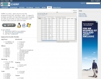 CHIRP is a free, open-source, cross-platform radio programming tool that supports a large number of transceivers from manufacturers such as Icom, Kenwood, Yaesu, Alinco, Wouxun, Puxing, and Baofeng. Chirp radio software run on Windows, Linux, and macOS, enabling users to exchange data between different radio models and interface with multiple data sources and formats. The program streamlines the configuration of memory channels, frequencies, and various settings for amateur radio handhelds. Specific models supported include the _Icom IC-7300_, _Kenwood TH-D74_, and _Yaesu FT-818_, among many others. CHIRP provides compatibility with various file formats, including Generic CSV, RT Systems CSV, ARRL Travel Plus (.tpe), and manufacturer-specific formats like Kenwood KPG-44D (.dat) and Icom Data Files (.icf). Additionally, it integrates with the DMR-MARC Database for enhanced programming capabilities. Users can download CHIRP for their platform and access extensive documentation, including a FAQ and a mailing list for support. The project encourages users to consult existing documentation and open/closed tickets before submitting new bug reports or feature requests.
 -
 Selecting an appropriate antenna system for shortwave broadcasting involves evaluating various types based on performance, cost, and operational parameters. This resource details the critical specifications for broadcast antennas, including average and peak power ratings, directivity, takeoff angle (TOA), horizontal beamwidth, and gain, emphasizing that a 100-kW transmitter requires an antenna rated for 150 kW average and 400 kW peak. It clarifies that low TOA signals travel thousands of kilometers, while high TOA is for local coverage, and nearly all modern shortwave broadcast antennas are horizontally polarized. The article explores specific antenna types, such as Log-Periodic Antennas (LPAs), which offer wide frequency ranges (e.g., 2-30 MHz) and directional patterns with 11 dBi gain, costing from $20K to over $100K for multi-curtain versions. Dipole arrays, also known as curtain antennas, are prevalent in international broadcasting, featuring steerable beams (±15° and ±30°) and mode-switching capabilities to alter TOA, with high/low pairs costing over $1 million. Fan dipoles are noted for omnidirectional patterns, smaller size, and lower cost for low-power applications, while rhombics, though simple, require resistive termination and incur several dB of I2R losses. Balun considerations are crucial, as most communications baluns are not rated for the higher average and peak powers of AM broadcast transmitters. Modern shortwave antennas utilize durable materials like Alumoweld wire rope for radiators and support elements, avoiding copper, fiberglass, or materials prone to stretching or deterioration. Feeder systems for high-power stations often require tapered-line baluns to convert 50-ohm unbalanced power to 300-ohm balanced for connection to the antenna.
 -
 The IndyScan website functions as a personal blog, documenting the author's experiences across various aspects of daily life, including travel, culinary adventures, and media consumption. Content frequently details personal trips, dining experiences in Indiana and other locations, and reviews of books, television shows, and products. The site also includes reflections on local events and personal purchases, providing a snapshot of the author's interests and activities. While the site's primary focus is personal narrative, it occasionally touches upon amateur radio, such as mentions of operating during a trip to Brookville, Indiana, or capturing a weather fax via shortwave radio. These ham radio-related entries are integrated within broader lifestyle updates, offering a glimpse into the author's engagement with the hobby rather than providing technical guides or detailed operational information. The resource serves as a personal journal, not a dedicated technical reference for amateur radio.
 -
 The Resonant Feedline Dipole (RFD) HF antenna design utilizes a single piece of coaxial cable and a stranded wire section, forming a 1/4-wavelength radiator. This configuration, based on a 1997 ARRL Handbook design (page 20.17), functions by RF traveling on the inside of the coax shield and returning on the outside, creating the second half of the dipole. A choke wound into the feedline prevents RF current from flowing back down the feedline. Construction details include using RG-58a/u coax for a 75m version, with a 1/4-wavelength section of stranded wire soldered to the center conductor. The document provides choke dimensions for RG-213, RG-8, and RG-58 coax across 3.5 MHz to 28 MHz, specifying cable length and number of turns. Dipole dimensions are also tabulated for frequencies from 3.6 MHz to 28.4 MHz, listing overall length and individual leg lengths. Field tests included deployment near Bryson City at 5 feet off the ground and as a sloper during WCARS Field Day in Asheville, yielding successful local and regional contacts.
 -
 A fractional bandwidth of up to 30:1 characterizes spiral antennas, making them highly effective across a very wide frequency range, often from 1 GHz to 30 GHz. The resource details two primary types: the **Log-Periodic Spiral Antenna** and the **Archimedean Spiral Antenna**, defining each with specific polar functions and illustrating their planar configurations. It explains that spiral antennas are typically circularly polarized, with a Half-Power Beamwidth (HPBW) of approximately 70-90 degrees, and a peak radiation direction perpendicular to the spiral plane. The content elaborates on critical design parameters affecting radiation, including the total length (outer radius) for lowest frequency, the flare rate ('a' constant) for optimal radiation versus capacitive behavior, the feed structure (often an infinite balun) for high-frequency operation, and the number of turns (typically 1.5 to 3 turns). It also discusses the theoretical impedance of 188 Ohms for Log-Periodic spirals, derived from Babinet's Principle, noting actual impedances are often 100-150 Ohms. The article presents a simple construction method for an Archimedean spiral, demonstrating VSWR and efficiency measurements. Measurements from a constructed spiral antenna show a VSWR that is fairly constant across the band, albeit with a mismatch loss of about 3 dB. The antenna efficiency remains around -5 dB (31.6%) across its operating range, indicating a decent wideband radiator despite opportunities for optimization.
 -
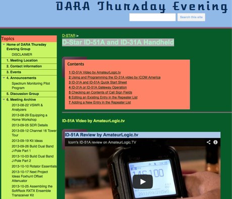 Manually programming D-Star handheld transceivers like the _Icom ID-51A_ and _ID-31A_ can be a straightforward process, enabling operators to configure repeaters, simplex frequencies, and D-Star specific settings without relying on computer software. This method is particularly useful for field operations or when quick adjustments are needed, allowing hams to set up callsign routing, DR mode, and reflector links directly from the radio's interface. Understanding the menu structure and key sequences is crucial for efficient on-the-fly programming. Operators often find manual programming invaluable for activating new D-Star repeaters encountered during travel or for participating in local nets where specific G2 or G3 gateway configurations are required. While software like _CS-51_ offers convenience for bulk programming, the ability to manually input frequencies and D-Star parameters ensures operational flexibility. This approach also helps hams troubleshoot connectivity issues by verifying individual settings directly on the transceiver, ensuring proper D-Star registration and gateway access.
 -
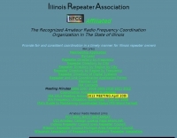 Effective operation of amateur radio repeaters, particularly in high-density areas, relies on coordinated frequency assignments to prevent interference. This resource from the _Illinois Repeater Association_ (IRA) serves as the official frequency coordination body for the state of Illinois, providing essential information for repeater owners and users. It details coordination policies, guidelines, and application forms for new and existing repeaters, ensuring fair and consistent spectrum utilization. The site also includes a comprehensive band plan, last revised in 2006, and a selective access policy (PL/Squelch Plan) updated in 2015, which are critical for maintaining orderly operations. The IRA website offers various repeater directories, sortable by frequency, city, and region, including a dedicated section for digital systems. These directories are invaluable for hams traveling through Illinois or setting up new repeater projects, helping them identify available frequencies and coordinated systems. The resource also provides meeting minutes, newsletters, and links to other regional repeater councils, demonstrating its role in fostering inter-state coordination. This structured approach to frequency management helps ensure reliable communications and minimizes QRM across the state, supporting thousands of repeater contacts annually.
 -
 Sporadic E is a form of propagation that can arise with little warning, and enable radio frequencies of 150 MHz and more to travel over distances of a thousand kilometres and more.
 -
 This document serves as a thorough guide to amateur radio nets throughout Australia and includes some international (DX) nets. It outlines key information like frequencies, schedules, and the people responsible for managing these nets. Among the nets covered are Ron's 10 A.M. net, the Australian Travellers Net, and several others, each operating on different bands and regions. Additionally, it offers technical details about repeaters, such as frequency, offset, and CTCSS tones where applicable. Any updates are clearly marked, and further details are included for linked repeater systems and network connections.