Search results
Query: if capacitor
Links: 58 | Categories: 0
-
 Details the construction of a **multiband vertical** antenna, specifically designed for stealth operation in a rented property, covering 80m, 60m, 40m, and 30m. The author, N3OX, leverages a 12m Spiderbeam telescoping fiberglass pole as the primary support, noting its sturdiness compared to typical fishing rods while remaining light enough for quick deployment and takedown. The radiating element is a 14 gauge Flex-Weave wire, attached to the pole's top with a rubber grommet, and fed by 27 bare 18 gauge radials spread across a 40-foot square backyard. N3OX describes the impedance matching solution, opting for custom-built L-networks over a remote tuner to enable fast bandswitching. Using an MFJ-259B and EZNEC modeling, base impedances were measured and component values calculated with G4FGQ's L_TUNER and SOLNOID_3 programs. The 80m coil is wound on a 3.5-inch PVC form, while the 30m, 40m, and 60m coils are air-wound, self-supporting #10 wire. Variable capacitors are incorporated for 40m and 30m shunt elements, with the 60m impedance matched by a series inductor. The project includes a **servo-controlled** homebrew band switch, utilizing a two-pole 12-position ceramic wafer switch for remote operation, addressing the limited 80m bandwidth. The entire matching network is housed in a weather-resistant shelter constructed from lumber and aluminum flashing. N3OX reports good DX results at 100W, estimating the total cost between $150 and $250, depending on existing parts.
 -
 Demonstrates the construction of a **remote antenna tuner** utilizing a standard radio-controlled (RC) servo mechanism to adjust a variable capacitor. The design focuses on enabling remote tuning for narrow-bandwidth antennas, specifically mentioning frame and packing crate antennas, from within the shack. It covers the mechanical arrangement for integrating the servo with a capacitor and provides a circuit diagram for a control unit that generates the necessary 0.5mS to 1.5mS pulse-width modulation (PWM) signals to drive the servo's 180-degree rotation. This setup was successfully tested with up to 20 watts RF power without arcing or adverse effects on the servo, though tuning was performed at 1 watt for VSWR readings. The resource highlights the use of inexpensive, readily available components, such as Futaba servos, and details critical considerations like power supply decoupling with a 47uF capacitor to prevent unintended servo movement upon power-off. The system provides a practical solution for optimizing antenna performance for specific frequencies without manual adjustment at the antenna itself.
 -
 The Flower Pot Antenna project details a portable dual-band antenna primarily operating on 10 meters, with secondary resonance near the 30-meter band. Construction involves winding RG58 coaxial cable uniformly around a large plastic flower pot, approximately 70cm high with a 60cm top diameter. The design eliminates the need for radials, contributing to its compact and lightweight nature. Key construction steps include soldering the inner conductor to the shield at one end of the wound cable and connecting the wound cable's shield to the rig cable's inner conductor at the base. An LC network, comprising a variable capacitor (0-200pF) and an inductor (10 coils, 5cm diameter, 2mm wire), is inserted between the wound cable's inner conductor and the rig cable's shield. Tuning is performed with an antenna analyzer, adjusting cable length and the variable capacitor for optimal impedance on 10 meters. The antenna performs effectively when installed horizontally.
 -
 Multiband Center-Loaded Off-Center-Fed Dipole (CL-OCFD) antenna that work on 80m 40m 30m 20m 15m 10m. The Center-Loaded Off-Center-Fed Dipole (CL-OCFD) antenna, developed by Serge Stroobandt, offers a versatile solution for amateur radio enthusiasts, covering multiple HF bands (80, 40, 30, 20, 15, and 10 meters) without the need for an antenna tuner. This innovative design utilizes a capacitor for resonance on the 80-meter band and a resistor to manage static charges. The CL-OCFD enhances bandwidth and simplifies operation, making it a significant advancement on OCF Dipole design.
 -
 Constructing a **2-meter** J-pole antenna from readily available copper plumbing components offers a robust and cost-effective solution for VHF operation. This design, dubbed the "Plumber's Delight," functions essentially as a half-wave dipole fed by 50-ohm coax via a **gamma match**. It incorporates a quarter-wave copper tubing support, which, when affixed to a metal mast or tower, enhances forward power in the direction of the radiating elements. The original configuration utilized a small ceramic trimmer capacitor for the gamma match, suitable for up to 10 watts. A subsequent modification replaced this with a 50 pF variable capacitor housed in a plastic enclosure, accommodating higher RF power and improving weather resistance. The antenna elements are secured using a copper "T" fitting, and an SO-239 connector mounts directly to this fitting. Performance includes gain away from the support mast, and tuning is straightforward by adjusting the gamma match capacitor for a 1:1 SWR. The total cost for materials, excluding the capacitor and coax, can be under $10.
 -
 Constructing an HF End-Fed Half-Wave (EFHW) vertical antenna, the resource details the winding of a monoband matching unit, inspired by _AA5TB_, designed to provide a 50 Ohm impedance match without a ground plane or antenna tuner. It specifies the use of a _T200-2_ ferrite core for the transformer, outlining the 13-turn secondary and 2-turn primary winding process with enamelled copper wire. The document also describes the integration of a coax capacitor, whose length is critical for tuning and varies by band, with specific starting lengths provided for 20m, 17m, 15m, 12m, and 10m operation. The practical application section guides the builder through tuning the antenna using an antenna analyzer, emphasizing the iterative process of spacing secondary windings and trimming the coax capacitor to achieve resonance at the desired band frequency. It highlights the antenna's low angle of radiation, beneficial for DX, and claims up to 2 S-points improvement over a _G5RV_ or similar doublet when used as an omnidirectional vertical. A comprehensive shopping list, including specific part numbers from _Rapid Electronics_, is provided, along with advice on selecting fiberglass fishing poles for support and suitable antenna wire.
 -
 End-Fed Half-Wave Antennas (EFHWAs) are analyzed for their utility in portable QRP operations, emphasizing their simplicity, efficiency, and predictable radiation patterns compared to other portable antenna types. The discussion contrasts EFHWAs with vertical antennas, random length wires, and center-fed dipoles, highlighting the common pitfalls of each, such as ground system dependency for verticals and feedline issues for dipoles. The article details the electrical half-wavelength calculation using the formula L (Ft) = 468/F(MHz) and explains how EFHWAs can be resonant on harmonic frequencies, enabling multiband operation. Various deployment configurations are presented, including the inverted L, inverted Vee, sloping wire, and vertical setups, each with specific advantages for radiation angle and polarization. For instance, a vertical EFHWA offers a low angle of radiation suitable for DX contacts without requiring an extensive ground system. The resource also addresses the counterpoise requirements, suggesting a quarter-wavelength wire or connection to a metallic structure for decoupling. A schematic diagram for a simple parallel-tuned circuit tuner, based on the _Rainbow Bridge/Tuner_ design, is provided, detailing component values for 30 and 40 meters, including a 6 microhenry toroidal inductor and a 20-100 picofarad mica compression capacitor. The tuner's adjustment process for SWR matching is also outlined.
 -
 Details a practical QRP wattmeter construction, leveraging a simplified SWR meter design by JA6HIC. The project focuses on a forward-only power measurement circuit, providing a functional instrument for RF power levels from milliwatts up to 5 watts. It maintains a 50-ohm input and output impedance, suitable for typical QRP transceivers and antenna systems. The resource includes the schematic for the "VSW" (Very Simple Wattmeter) and outlines a six-step alignment procedure. This calibration process involves using a known RF source up to 5W, setting full-scale deflection, and marking power increments. It also addresses minimizing frequency effects on readings with a 100pF trimmer capacitor, noting that measurement error is highest at the lower end of the scale. Construction notes mention using a piece of RG-213 coaxial cable for the inductance and coupler, with the wattmeter assembled in early 2003. The author provides an example measurement showing 0.8W into a dummy load and 1W into a 3-element beam.
 -
 Constructing a compact, two-band magnetic loop antenna for HF operation, especially from constrained locations like a balcony, presents unique challenges. OK1FOU's design, inspired by DJ3RW's 50 MHz loop, addresses these by employing an unusual side-fed configuration and placing the symmetric, two-section variable tuning capacitor at the bottom of the loop, directly connected to the coax shield. The article provides specific material recommendations, including two 1-meter wooden pales and about 3 meters of thick loudspeaker cable, noting the high current (60A at 100W) in the loop. Construction steps detail forming two turns with a 5 cm gap, using a GDO to pre-tune the open loop to a frequency slightly above the desired highest band, and then integrating the tuning and coupling capacitors. For 10/14 MHz, an open loop resonance of 16-17 MHz is suggested. Practical experience with the 10 MHz band from a third-floor balcony in Prague (JO70GC) shows a 1:1 SWR across most of the band without an external ATU. While DX traffic was modest due to the urban environment, QSO examples with RA6WF, LA6GIA, G0NXA, and LZ1QK on 10 MHz are provided, demonstrating its operational capability.
 -
 The W1TAG LF Receiving Loop is a specialized antenna project for LF reception, designed to mitigate local noise and enhance weak signal pickup on the lower frequencies. This square loop, measuring 6 feet per side, utilizes 14 turns of #12 THHN wire wound on a PVC frame, offering a robust mechanical structure. The design incorporates a series-tuned circuit with a coupling transformer, allowing for tuning from over 400 kHz down to _45 kHz_ using a switched capacitor bank. Construction details include the use of 1.5-inch PVC pipe for the frame, with specific measurements for spreaders and drilled holes for wire threading. The two 7-turn sections of wire are connected at the center, providing an option for a center tap. The loop rotates on a 1-inch steel pipe, enabling directional nulling of noise sources. The tuning unit, housed in a box clamped to the PVC, employs a 1:2 step-up transformer wound on an _FT-82-77 core_ and uses relays to switch capacitance values from 50 pF to 6400 pF, providing precise frequency adjustment. The current setup connects to the shack via 100 feet of RG-58, feeding into a W1VD-designed preamp, with plans for a balanced, shielded twisted pair cable upgrade.
 -
 Demonstrates practical solutions for reducing **Radio Frequency Interference (RFI)** in amateur radio operating environments, specifically addressing issues with PC monitors, receivers, and transceivers. The resource compiles advice from experienced operators regarding the selection and application of ferrite cores, including split cores and toroidal cores. It details specific material types like **43, 73, 75, and 77 ferrite**, outlining their effective frequency ranges for RFI suppression, such as 43 material for 30-400 MHz and 77 material for 2-30 MHz. The content provides part numbers for various ferrite products from manufacturers like Fair-Rite Products Corp, distributed by Amidon, and discusses their impedance characteristics across different HF bands. It compares the performance of various ferrite materials at frequencies like 4 MHz, noting that 75 material offers 27 ohms, 73 material 17 ohms, and 43 material just under 10 ohms. Additionally, it touches upon the use of bypass capacitors in conjunction with ferrites to create low-pass filters, emphasizing the importance of identifying common-mode versus differential-mode RFI paths for effective mitigation.
 -
 One specific challenge in the KazShack, operating Single Operator Two Radios (SO2R), involved sharing a K9AY receive antenna between two transceivers without direct RF connection or manual feedline swapping. The solution, detailed in this project, adapts the **W3LPL RX bandpass filter** design to split 160m and 80m signals, feeding them to separate radio inputs while maintaining isolation. This approach also addresses the issue of strong broadcast band interference from a nearby 50KW WPTF transmitter on 680kc. The construction utilizes T-50-3 toroids and NP0 ceramic capacitors, built in a "dead bug" style on copper clad board. Each band's filter coils are identical and resonated to the desired frequency using an MFJ-259 antenna analyzer. A single DPDT relay, controlled by a remote toggle switch mounted on an aluminum panel, facilitates quick band switching between radios, simplifying low-band operations. While some signal loss is noted, the expected lower noise levels from the receive antenna are anticipated to compensate, potentially reducing the need for constant volume adjustments during toggling between transmit and receive antennas.
 -
 Over 1,000 stations in approximately 60 countries were worked using this modified twin-lead folded dipole, demonstrating its effectiveness with just 4 watts on 20 meters. This design, adapted from an ARRL Handbook concept, eliminates the shorting strap found in traditional folded dipoles, simplifying construction while maintaining performance. It utilizes readily available 300-ohm TV antenna feeder ribbon, making it a cost-effective solution for radio amateurs. The antenna's robust construction allows it to handle up to 100 watts without issues, even without a **balun**. The inclusion of a variable trimmer capacitor at the stub provides flexibility for tuning across different frequencies within a band, a practical feature for operators using transceivers like the Icom 735. Formulas are provided to calculate the precise dimensions for any desired operating frequency, enabling customization for various **HF bands**.
 -
 The Collins TRC-75 autotune linear amplifier, owned by JF2SVU, is presented with a focus on its internal modifications. This QRO amplifier utilizes three 4CX250 tubes in parallel for its final stage, delivering 1 KW output power. Notably, the amplifier achieves full power with only 100 mW of RF input, a characteristic often associated with Collins designs. The original 400 Hz power supply has been converted for easier shack integration, and the entire RF and power supply sections have been rehoused into a compact, clean enclosure. The control unit, positioned above the amplifier, features three meters for individual vacuum tube IP monitoring and a multi-meter on the right. A dedicated 7 MHz receiver, recently completed, is also part of this integrated system. The autotune functionality means the main amplifier unit only requires connections for power, control, and coaxial cables, simplifying its operation. Key components like the 4CX250 tubes and NF capacitors are visible, along with the gearing mechanism for the final tank circuit. A timer and relay system manages high-voltage delay and cooling fan off-delay, although the cooling fan's airflow is noted as somewhat insufficient. A central volume control, which experienced a contact issue, is also highlighted.
 -
 This article explores the claim an amplifier might arc from a parasitic oscillation, damaging capacitors, bandswitches, or other components.
 -
 A 4 AMP / 18V regulated power supply schematic, designed by _ON6MU_, provides a detailed circuit diagram for constructing a robust power source. The design focuses on delivering a stable 18-volt output at up to 4 amperes, crucial for powering various amateur radio equipment. This resource presents a clear visual representation of component interconnections, including rectifiers, filter capacitors, and voltage regulation stages, essential for DIY enthusiasts building their shack infrastructure. The schematic's clarity facilitates understanding the power flow and component roles within the circuit. This circuit design offers a practical solution for hams needing a reliable 18V supply, potentially useful for driving specific transceivers, amplifiers, or accessory circuits. While specific performance measurements or comparisons to other designs are not detailed, the schematic itself serves as a foundational blueprint. Builders can adapt or modify the _power supply_ to suit their particular needs, such as integrating overcurrent protection or fine-tuning the output voltage with adjustable regulators. The straightforward presentation makes it accessible for those with basic electronics knowledge to assemble and troubleshoot.
 -
 Optimizing the ZS6BKW antenna for full HF band coverage often requires specific modifications beyond its standard configuration. This resource details several enhancements, beginning with a simple series capacitor to improve 80m SWR, a technique W5DXP found effective for permanent installation due to its minimal impact on higher bands. Further improvements include a 10-inch parallel open stub for 10m resonance, shifting the frequency to 28.4 MHz with an SWR of approximately 1.8:1, a practical solution for Technician class operators. The document then explores a switchable matching section, adding or subtracting one foot of ladder line at the 1:1 choke-balun, which significantly impacts higher frequency bands and eliminates the need for a tuner on 17m. W5DXP's _AIM-4170D_ antenna analyzer measurements confirm these effects. More advanced modifications involve a parallel capacitor for further 80m SWR reduction, requiring remote switching for multi-band operation, and relay-switched parallel capacitors at specific points on the 450-ohm matching section to achieve low SWR on 60m, 30m, and 15m. These detailed steps, including _Smith chart_ analyses for the challenging bands, aim to transform the ZS6BKW into a truly all-HF-band antenna, reflecting W5DXP's practical experience in antenna tuning.
 -
 Presents a QRP AM/CW transmitter project specifically designed for the 10-meter band, utilizing a crystal oscillator and a collector-modulated AM oscillator. The design employs a 2N2219(A) transistor in a Colpitts configuration, generating 100 to 350 mW of RF output power depending on the 9-18 Volt supply voltage and modulation depth. Frequency stability is maintained by a 28 MHz crystal, with fine-tuning possible via a Ct1 trimmer capacitor for approximately 1 kHz adjustment. The resource details the RF oscillator stage, implemented with a 2N2219 NPN transistor, emphasizing frequency stability and low power dissipation. It also covers the amplitude modulation stage, managed by a 2N2905 PNP transistor, which impresses audio information onto the carrier. Selective components (C3, C4, C7, C5) enhance voice frequencies within a +/- 5 kHz bandwidth, and modulation depth is controlled by R2 and R3. The project includes a 3-element L-type narrow bandpass filter (Ct3, L3, C10) to suppress harmonics and ensure a clean output signal. The project provides a complete schematic diagram, a comprehensive parts list including specific capacitor, resistor, and inductor values, and construction notes for the coils (L1, L2, L3). It also offers practical advice on enclosure requirements, suggesting an all-metal case or a PVC box with graphite paint for RF shielding. Operational parameters such as current draw (27mA@9V to 45mA@16V) and input impedance (50 Ohms) are specified, alongside guidance on antenna matching and the importance of a valid amateur radio license for 10-meter band operation.
 -
 Svetlana tubes also Russian capacitors,vacuum and coaxial relay, for RF Power Linear Amplifier builders. Amateur-Radio, Broadcast. Full Online Catalog.
 -
 The Elecraft K2 transceiver requires specific modifications for optimal soundcard digital mode operation, particularly for PSK31. The original article, circa 2001, details initial challenges with manual PTT and speech compression settings. A key modification involves adding headphone audio and a compression disable signal to the K2's microphone jack, utilizing pins 4 and 5. The **COMP0** signal, active low, is shorted to ground via a non-inverting open collector switch circuit, comprising two resistors and two transistors, mounted on the SSB board near U3. This circuit provides effective control of an analog signal line with good noise immunity. The switchbox itself repurposes a computer COM port switch, using only two of its original connectors and four of the nine poles. It integrates a microphone preamplifier, a PTT circuit built with 'flying leads' construction, and RCA jacks for soundcard connections. A trimpot adjusts the audio drive to the K2. The central DB9 connector links to the K2's mic connector via a shielded RS232 serial cable, ensuring proper grounding and signal routing. An external footswitch PTT jack is also included. Further enhancements include a **noise-canceling microphone** preamp based on a QST December 2000 article, adapted for Heil mic elements. This preamp, built with pseudo-Manhattan style construction, provides a gain of approximately 2 by changing emitter resistors (R9 and R16) from 680 ohms to 330 ohms. A 10-ohm series resistor and 47 µF capacitor on the +5V supply mitigate noise spikes.
 -
 1500 watts PEP output from a Kenwood TL-922 amplifier requires careful attention to parasitic suppression and component selection to ensure stability and longevity. This resource critically examines common modifications, often based on anecdotal evidence rather than sound engineering principles, that can degrade performance or introduce new issues. It highlights how replacing aged components often gets misattributed to the efficacy of unnecessary modifications, leading to widespread misinformation within the amateur radio community regarding amplifier stability. The article details specific, effective modifications for the TL-922, such as shortening anode-to-chassis and anode-to-grid paths to improve VHF stability and efficiency. It addresses issues like incorrect capacitor types in the tank circuit, inadequate grid grounding, and poor RF sheet metal design, providing practical solutions like adding direct ground connections for the plate tune variable capacitor. The author also discusses proper parasitic suppressor design, emphasizing the importance of lead length and component selection for optimal performance and harmonic suppression, contrasting these with less effective or detrimental 'magical suppression kits'.
 -
 The resource details the construction of a homebrew 50-watt FET amplifier, based on Don W6JL's _QST Homebrew contest_-winning design from 2009. It functions as an afterburner for QRP transceivers, providing a **12dB** power lift. The amplifier utilizes IRFZ24N FETs and covers the 80, 40, 30, and 20-meter bands, with the 20m LPF extending to 17m. Key technical aspects include an FT37-43 transformer for the input network, a relay-switched 3dB pad for lower bands controlled by an _Arduino Nano_, and an RF-actuated T/R switch. The LPF board integrates four relay-switched filters rated for 50 watts, using capacitors with a minimum 250VDC rating. Performance measurements indicate a power gain ranging from **4.4dB** on 20m to 8.1dB on 80m, with a required drive power of approximately 5 watts. The article also discusses thermal management, current limiting considerations, and component sourcing.
 -
 A system designed to automatically tune small transmitting magnetic loop antennas, particularly beneficial for **contest operations** where rapid frequency changes are common. The core of the system involves a PC-based control application, AutoCap, written in C#, which monitors antenna SWR via an external meter and commands a motor interface to adjust the loop's variable capacitor. The software is compatible with Windows and Linux via the Mono framework, offering a graphical user interface for monitoring system status, SWR, power, and motor commands. Key components include one or more magnetic loop antennas equipped with DC or stepper motors for capacitor adjustment, an SWR meter with data output (such as the Telepost LP-100A or a homebrew serial/USB SWR meter), the AutoCap PC software, and a motor interface. The most effective motor interface utilizes an **Arduino-based controller** with custom firmware, providing precise control over both simple DC motors and stepper motors, and supporting features like motor braking for finer adjustments. The system allows for configurable SWR thresholds, pulse widths, and motor effort settings to optimize tuning speed and resolution. Optional radio integration provides frequency hints, enabling the algorithm to learn the relationship between motor actions and resonant frequency, thereby speeding up initial tuning responses. The software also supports antenna profiles, allowing operators to save and recall specific configurations for different loops, including accumulated frequency hint data.
 -
 Mitigating RF noise in a mobile operating environment, particularly within a _Jeep TJ_ vehicle, presents unique challenges due to the vehicle's electrical system and chassis characteristics. This resource details practical methods for identifying and suppressing various forms of radio frequency interference (RFI) that can degrade receiver performance for both CB and amateur radio transceivers. It covers common noise sources such as ignition systems, alternators, fuel pumps, and computer modules, explaining how these components generate broadband or specific frequency noise that impacts radio communications. The guide offers actionable solutions, including proper grounding techniques, the strategic use of ferrite beads and toroids on power and data lines, and the installation of bypass capacitors. It discusses the effectiveness of different filtering strategies for DC power lines and antenna feedlines, illustrating how a clean power supply and shielded cabling can significantly reduce conducted and radiated noise. The information presented helps operators achieve a lower noise floor, improving signal-to-noise ratio and enabling clearer reception of weak signals, which is crucial for effective mobile DXing or local ragchewing.
 -
 The resource details the construction of a multiband trap-style Inverted-V antenna designed for operation on 3.5 MHz, 7 MHz, 14 MHz, 21 MHz, and 28 MHz. It presents specific winding data for the traps, including the number of turns, wire gauge, and coil former dimensions, crucial for achieving resonance on the target bands. The document provides a parts list and a diagram illustrating the antenna's physical layout and trap placement. It outlines the process for building the traps using PVC pipe formers and specifies the required capacitor values for each trap. The design emphasizes a practical approach to achieving multiband operation with a single feedline, a common goal for HF operators with limited space. The document includes a table with antenna segment lengths for each band, allowing for precise replication of the design. It also offers insights into tuning and adjustment, ensuring the antenna performs optimally across the designated amateur radio bands.
 -
 Supplying over 2000 different vacuum tube types, valves, grid caps, sockets and capacitors. It is easy for Antique collectors, Ham radio operators, audio enthusiasts, broadcast enthusiasts and amateur radio hobbyists to buy, sell and trade vacuum tubes, electron tubes, audio tubes, valves, grid caps, sockets and capacitors
 -
 Air conditioning soft copper tubes are perfect for loop construction. If you want to try a loop you must have an air variable capacitor or a vacuum variable capacitor. Article by PY1AHD
 -
 Constructing a high-power 70cm solid-state amplifier presents unique challenges, particularly when aiming for 500 watts output using modern LDMOS devices. This resource details the author's experience building a 70cm amplifier based on a _Freescale MRFE6VP5600H_ transistor, initially from an RFHAM kit. It meticulously outlines the necessary modifications to achieve advertised performance, including optimizing input and output matching, correcting bias circuitry, and ensuring proper output balun connections for stability. The author shares specific adjustments, such as trimming the prototyping board for better transistor fit, drilling additional mounting holes for improved heat sinking, and replacing original matching capacitors with a single _20pf MIN02 metal mica_ for superior output. A critical fix involved jumpering gate decoupling pads to balance the push-pull transistor halves, which increased output to 580W and improved IMD. The resource also highlights a crucial correction to the output balun connection, initially reversed in the _Dubus_ article schematic, which resolved intermittent stability issues. Test results are provided, showing input power, output power, and drain current at 50V, demonstrating the amplifier's performance after modifications. This practical account offers valuable insights for hams undertaking similar high-power UHF amplifier projects, especially those working with LDMOS devices and kit-based constructions.
 -
 The _Sci.Electronics FAQ: Repair: RFI/EMI Info_ document, authored by Daniel 9V1ZV, provides a detailed analysis of computer-generated RFI/EMI, focusing on its impact on radio reception. It identifies common RFI sources such as CPU clock rates (e.g., 4.77 MHz to 80 MHz), video card oscillators (e.g., 14.316 MHz), and even keyboard microprocessors, all of which generate square-wave harmonics across HF and L-VHF regions. The resource outlines a systematic procedure for pinpointing RFI origins, including disconnecting peripherals and using a portable AM/SW receiver with a ferrite rod antenna to localize strong interference sources. The document categorizes RFI mitigation into shielding, filtering, and design problems, offering practical solutions for each. It recommends applying conductive sprays like _EMI-LAC_ or _EMV-LACK_ to plastic casings of radios, monitors, and CPUs to create effective Faraday cages, emphasizing proper grounding and avoiding short circuits. For filtering, the guide suggests using line filters, ferrite beads, and toroids on power and data lines, and small value capacitors (e.g., 0.01 uF for serial/parallel, 100 pF for video) to shunt RFI to ground. It also discusses the use of bandpass, high-pass, low-pass, and notch filters on the receiver front-end or antenna feed to combat specific in-band noise.
 -
 The page provides circuit improvements for the Kenwood TS-440S transceiver, addressing issues such as distortion in SSB signals, limited transmit frequency coverage, lack of crispness in RX audio, and flat audio response. The fixes include adjusting bias, cutting specific components, and changing capacitors to improve performance.
 -
 This online project guide details the construction of a homebrew boom microphone system. It details the assembly of a microphone shell from a 3/4" PVC pipe section and an end cap, requiring a drilled hole for a snug fit of the electret or condenser mic element. The internal wiring schematic specifies a **2.2 K** resistor and a **47 uF** polar capacitor for signal conditioning, with a circuit diagram provided for integration with IC-706 series transceivers. The guide outlines the use of CAT-5 cable for internal connections, incorporating strain relief at the rear of the mic shell, and an inline 3.5 mm jack to facilitate an external _PTT_ line, designed for a foot-mounted switch. Further construction involves fabricating a microphone shock mount from a 2-inch PVC connector, detailing the creation of four "fingers" and the insertion of screw-eyes for attaching elastic bands, which are twisted 180 degrees for tensioning and vibration isolation. A foam wind screen is also incorporated into the microphone assembly, secured with adhesive. The boom arm itself is repurposed from an articulated architect lamp, with the original lamp assembly converted into a **60 watt** resistive load for testing power sources. Microphone cabling is secured to the boom arm using wire ties, ensuring sufficient slack at hinge points to maintain articulation. The boom base is mounted to a bookshelf, requiring specific positioning to achieve proper microphone placement in front of the operator. Performance evaluation of the microphone system is conducted through on-air audio signal reports from other amateur radio operators. DXZone Focus: Online Project Guide | Boom Microphone Construction | Electret Mic Element | PTT Line
 -
 Mobile RFI, often manifesting as persistent noise in the receiver even with the antenna disconnected, frequently originates from the vehicle's power supply system. This guide details systematic troubleshooting steps, beginning with isolating the radio from the car's 12-volt supply to confirm the power system as the noise source. It emphasizes the critical importance of drawing power directly from the battery using **heavy gauge wire**, bypassing the fuse block to leverage the battery's natural capacitance for RFI suppression and ensuring a solid RF ground. Proper routing of power lines through the firewall is also covered, advocating for dedicated grommeted holes to prevent inductive coupling from other wiring harnesses. The article stresses the necessity of fusing both positive and negative leads from the battery, a crucial safety measure to prevent damage to the rig and mitigate high-current risks should the battery's engine block ground become compromised during service. Addressing **alternator whine**, a common high-pitched noise that varies with engine speed, the resource suggests checking battery connections and the alternator-to-battery harness for looseness or corrosion. It also mentions the utility of adding an external RF noise suppression capacitor in parallel with the alternator's internal capacitor for enhanced filtering, and the effectiveness of commercially available in-line power supply filters.
 -
 The AT-AUTO automatic antenna tuner handles 1.5kW CW operation, employing stepper motors under microprocessor control to precisely position a roller inductor and air-dielectric variable capacitor, avoiding relay-switched discrete components. This design choice prevents loud relay clacking and burning contacts, a common issue with competing products. The tuner features auto-retuning capabilities and receives periodic firmware updates, ensuring continuous improvement and added user-requested features. Its companion product, the _CX-AUTO_ coaxial switch, also features an embedded microprocessor controller. It enables selection of 1-of-8 coaxial outputs via a serial data interface. When integrated with the _AT-AUTO_, the tuner can associate specific coaxial outputs with amateur radio bands, automatically commanding the _CX-AUTO_ to select the correct antenna when the operator QSYs to a different band. Don Kessler began designing the AT-AUTO in 2005, with its debut at the 2006 Dayton Hamvention. Kessler Engineering also offers custom RF product design and electrical engineering consulting, specializing in Class-E RF amplifiers.
 -
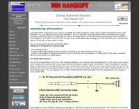 Demonstrates the fundamental principles for connecting a personal computer to a ham radio transceiver, specifically for utilizing sound card-based digital mode software like those in the MM Hamsoft suite. It details the basic hardware setup, emphasizing the use of shielded leads and proper audio routing from the radio's output to the sound card's input, and from the sound card's output to the radio's microphone or data input. The resource highlights the critical need for transmit attenuation, suggesting a 100:1 voltage divider to prevent overdriving the transmitter's audio stage, and mentions the optional addition of ferrite beads and decoupling capacitors for RFI mitigation. The guide also points to external resources for more detailed pin-outs and interface schematics, such as a specific QSL.net page, and recommends consulting the help files within MM Hamsoft programs for interfacing specifics. It underscores that while the process is straightforward, understanding the audio level management and proper cabling is key to successful operation. The author, VE5KC, provides practical advice drawn from common issues encountered by operators setting up digital mode stations.
 -
 The MFJ-971 portable antenna tuner, as stock, lacks a bypass switch and sufficient inductance for efficient 1.8 MHz operation. This modification addresses these limitations by integrating a DPDT switch for direct signal bypass, enhancing operational flexibility. Furthermore, the guide details the addition of a T130-2 iron powder toroid, wound with **29 turns** of enamelled copper wire, to augment the tuner's internal inductance. This increases the maximum inductance from approximately 17µH to around **27µH**, enabling effective impedance matching on the _160-meter band_. The modification involves cutting the wire after the 'L' tap on the original inductor and inserting the additional toroid, ensuring the entire original coil plus the new inductance is engaged when 'L' is selected. This preserves the functionality of other inductance settings while extending low-band performance. The article also highlights a potential RF burn hazard from the variable capacitor nuts on the MFJ-971, even at QRP power levels.
 -
 Brugtgrej presents a Danish online classifieds platform specifically for amateur radio operators and electronics enthusiasts. The platform facilitates the buying and selling of used equipment, including transceivers like the Icom IC-7410, various components such as X'TAL FILTER FMT-15A and TRANSISTOR 2SC3019, and accessories like Sadelta microphone capsules and SMA to SMA extenders. Users can post free advertisements for items they wish to sell or acquire, covering categories beyond amateur radio, including antique radios, military radios, and radio tubes. The site lists active advertisements, with 3136 online ads and 167 online users at the time of analysis, indicating a dynamic marketplace. It also features a forum for community interaction, discussing topics like repeater rings on 1297 MHz and FT8 activity. The platform's structure supports both 'Sælges' (for sale) and 'Købes' (wanted) listings across its various sections. Specific items observed include a Miniwatt pentode 4689, various capacitors and coils, and general electronic components, demonstrating the breadth of offerings available to the amateur radio community.
 -
 Amateur Packet Reporting System (APRS) operations often require compact, reliable solutions for transmitting position data, particularly for mobile or portable stations. This resource details the construction of the _Tiny Track-I_, a transmit-only APRS tracker designed for straightforward integration with a VHF radio and a Global Positioning System (GPS) receiver. It enables hams to broadcast their location without the complexity of a full-duplex TNC. The project outlines the printed circuit board (PCB) layout and schematic, based on an original design by N6BG, with a personal PCB drawing by SV1BSX. It includes specific component placement and notes an additional 10uF/10V capacitor (C5) for improved IC voltage decoupling, a modification not present in the original N6BG diagram. The unit connects to a computer or GPS via a DB9 female connector. This tracker is ideal for basic position reporting, offering a simple and effective way to participate in APRS networks. Its small footprint makes it suitable for vehicle installations or field deployments where space is limited, providing a **reliable 9600 baud** data stream for location updates.
 -
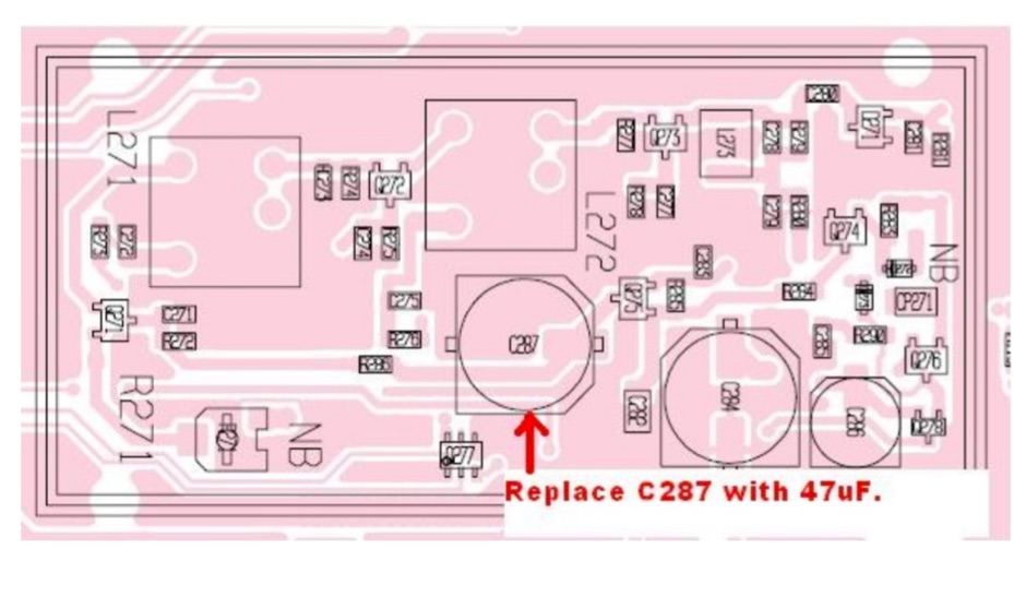 If your 756 has lots of noise with crackles and sweeping heterodynes, especially noticeable on AM, it may be due to a faulty electrolytic capacitor in the noise-blanker circuit
 -
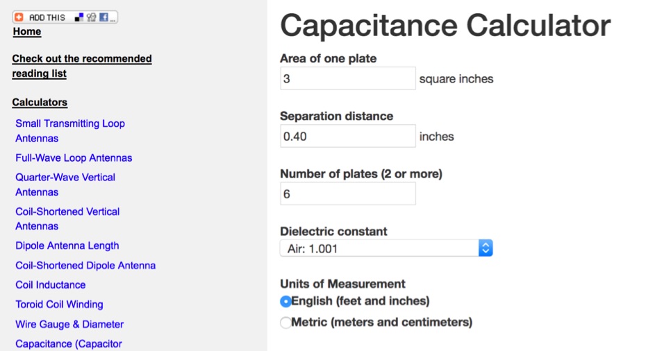 An online calculator for designing and evaluating capacitors based on the capacitor's area, separation, number, and dielectric constant
 -
 The _RS Group_ (formerly Distrelec) provides a comprehensive online store for electronic components, catering to both industrial and amateur radio needs. This resource offers a wide array of parts, including semiconductors, capacitors, resistors, relays, sensors, and power supplies, essential for constructing and maintaining amateur radio equipment. The platform emphasizes efficient procurement and features various top-level categories for easy navigation, such as **Sensors** with 33 subcategories and **Relays** with 13 subcategories, supporting diverse project requirements. Beyond component sales, RS Group offers services like ISO- and DAkkS-certified calibration for over a thousand measuring devices, and e-procurement solutions for businesses. The site also promotes _DesignSpark_, a community and software suite for electronic designers, aiding in the realization of design ideas. This integration aims to provide enhanced local support and a broader product selection, facilitating everything from basic circuit builds to complex industrial automation projects.
 -
 HAM-made engineering products supplies and produces coaxial relays, antenna switches, sequencers, roller inductors, variable capacitors, low noise preamplifiers, RF power rotary switches and coil bodies.
 -
 Building an End-Fed Half-Wave (EFHW) antenna from a kit, as detailed by Frank Bontenbal, PA2DKW, with process photos by Bob Inderbitzen, NQ1R, offers a practical approach for hams. This specific kit, a collaboration between ARRL and HF Kits, targets 10, 15, 20, and 40 meters, making it a versatile option for HF operations. Unlike a center-fed dipole, the EFHW is a half-wavelength antenna fed at one end, which simplifies deployment, particularly for portable use. The construction guide meticulously outlines the assembly of the 49:1 impedance matching network, crucial for transforming the antenna's high impedance (around 2,500 Ohms) to a transceiver-friendly 50 Ohms. Steps include preparing the enclosure by drilling holes for the coaxial connector and antenna connections, followed by the precise winding of enameled copper wire onto a toroid to create the transformer. The guide emphasizes careful insulation removal and soldering for reliable connections. Final assembly involves integrating a 100 pF capacitor for higher band compensation, soldering the transformer's primary and secondary sides, and conducting SWR tests with a 2K7 resistor or a half-wavelength wire. The document also provides examples of wire lengths for different bands, such as 16 feet for 10 meters or 66 feet for 40 meters, demonstrating the transformer's adaptability for various half-wavelength configurations.
 -
 A simple superheterodyne receiver (3.5–30 MHz) for amateur radio achieves stable SSB-CW reception using modern BJTs, an AD831 mixer, a 6-pole quartz filter, and Seiler oscillators. Designed with high IF (4.5 MHz), compact AM-FM variable capacitors, and modular resonant circuits, it ensures selectivity, image rejection, and stable tuning. Built in a copper-lined wooden case, it features practical assembly techniques but lacks advanced features like AGC or S-meter. Effective on basic antennas, it achieves global reception.
 -
 This article describes the construction of a three-band vertical antenna for the WARC bands (10, 18, and 24.9 MHz). Unlike a previous design using thin wire requiring a complex matching device, this version uses a telescopic set of pipes, reducing reactances and simplifying the matching device to two coils and two capacitors. The article provides details on the antenna model, the matching device circuit, and tuning methods, including the use of frameless coils and variable capacitors. With proper tuning, the antenna achieves a VSWR not exceeding 1.3 across all bands, demonstrating a practical and efficient design for amateur radio enthusiasts.
 -
 A medium power End Fed Half Wave Antenna coupler, specifically tuned to the QRP frequency of 7030 kHz. Constructed from coil stock and capacitors, it achieves an impedance ratio of 64:1. The coupler has proven effective for power ranges from 2 to 100 Watts on the 40m band.
 -
 This tutorial provides detailed instructions for constructing a DIY magnetic loop antenna, ideal for amateur radio operators seeking efficient short wave communication. The design features a remote tuning system utilizing an Arduino and RC servo, making it suitable for indoor use where larger antennas cannot be installed. Magnetic loop antennas are compact and can operate effectively in confined spaces, but they do require careful handling due to the high voltages and currents they generate during operation. Users should possess the necessary technical skills to implement this project safely. The tutorial includes a comprehensive overview of the antenna's theory, specifications, and mechanical design. It outlines the components needed, including a Soviet-made variable capacitor and a digital RC servo for tuning. Safety precautions are emphasized, as the antenna can produce several kilovolts of voltage and high currents. The project is not certified for safety, and users are advised to proceed at their own risk. The tutorial also provides diagrams and explanations of the antenna's operation, making it a valuable resource for both beginners and experienced operators looking to enhance their setup.
 -
 A Magnetic Loop Controller project details the construction and operation of an automatic tuning system for magnetic loop antennas, which are resonant circuits using an oversized inductor and an adjustable capacitor. The system employs a stepper motor to precisely adjust the variable capacitor, maintaining optimal resonance across the HF bands. It integrates with various transceivers, including _Icom_, _Kenwood_, and _Yaesu_ models, by monitoring the VFO frequency and adjusting the loop's tuning accordingly. The project provides comprehensive building instructions, a PowerPoint-style presentation, and the full source code for the controller's firmware, enabling hams to replicate and customize the design. The controller's firmware offers diverse functionality, including automatic frequency tracking, manual tuning, and SWR monitoring, significantly enhancing the operational efficiency of magnetic loop antennas, particularly for QRP and portable operations. The design emphasizes accurate capacitor positioning, crucial for achieving low SWR and maximum radiated power. Comparisons with manual tuning methods highlight the benefits of real-time adjustment, especially when operating across different bands or making frequent QSYs. The project's detailed documentation and available source code facilitate experimentation and modification by advanced builders, allowing for tailored performance characteristics.
 -
 Removing disturbing RFI from the Behringer HA400 Headphone Amplifier, using ferrites and capacitors soldered in the main circuit board of the small amplifier.
 -
 A small magnetic loop antenna, often employed by hams facing antenna restrictions or high local RFI, offers a compact solution for HF operation. This resource details the construction of a foldable magnetic loop designed for the 40m through 17m bands, emphasizing its high-Q factor and _Faraday coupling_ for effective noise rejection and narrow-band filtering. The guide outlines material selection, advocating for copper over aluminum to maximize efficiency, and provides insights into the physics governing its operation, including impedance matching and resonance principles. Practical application of this antenna design is particularly beneficial for QRP enthusiasts and portable operators seeking a stealthy, high-performance antenna. The construction process includes specific details for a 1-meter diameter loop, a 140pF variable capacitor, and a _gamma match_ for impedance transformation. Performance comparisons suggest that while a full-size dipole might offer slightly better gain, the magnetic loop's ability to mitigate local noise often results in a superior signal-to-noise ratio, making it a viable option for challenging RF environments.
 -
 This article details the author's process of designing and building a trap dipole antenna for the 17, 12, and 6-meter amateur radio bands using a Yaesu FT-450 transceiver. The antenna incorporates parallel-tuned circuit traps to enable operation across multiple bands without switching aerials. Key construction details, including coil and capacitor specifications, are discussed, along with the testing results, which include successful long-distance communications on the 50 MHz band. The article highlights the flexibility of home-built antennas and provides insights for amateur radio enthusiasts looking to optimize multi-band performance.