Search results
Query: 70cm antenna
Links: 69 | Categories: 1
Categories
-
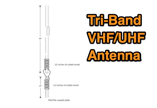 The TBJ-1 – a triband base antenna was published in March 2017 QST. This antenna covers 2M/220 MHz/70cm in one 6ft 3/4 inch PVC pipe and requires no radials.
 -
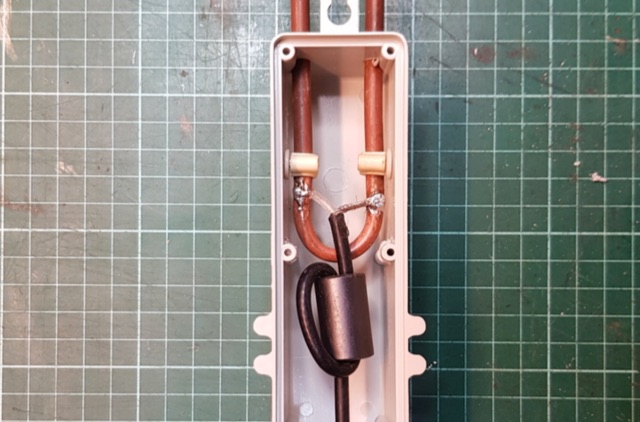 A homemade Jpole antenna for 70 cm band made with 6mm copper pipe
 -
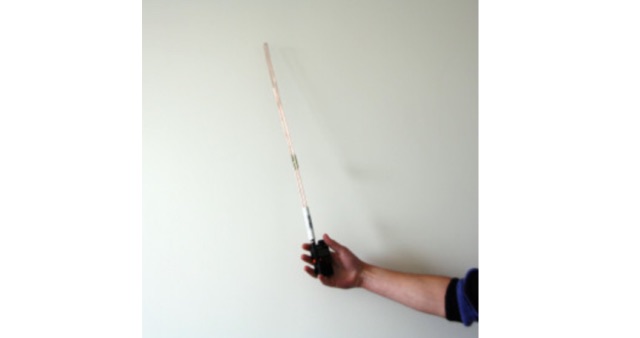 A simple slim jim antenna for 433 MHz. Simple drawings and pictures of a simple Slim Jim antenna.
 -
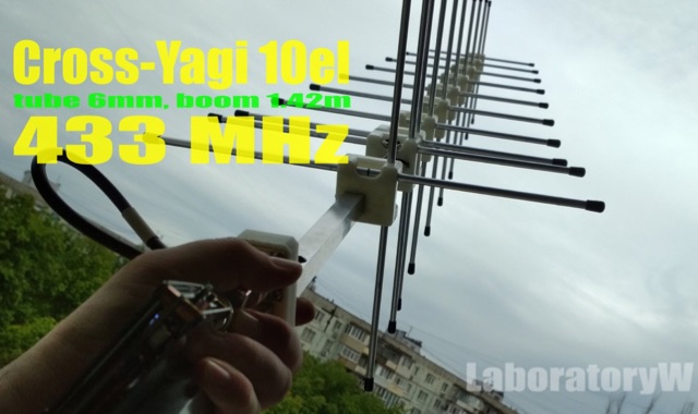 10 Elements Cross-Yagi Antenna for 433 MHz. The base of the 10el antenna is the recalculated RA6FOO antenna.Circular polarization is realized - by a phasing quarter-wave line, matching of horizontal and vertical polarization antennas
 -
 Homebrewing a UHF antenna to be used on a bicycle. This simple project gives you the right hints on how to build and setup and install a 70cm antenna on a bicycle.
 -
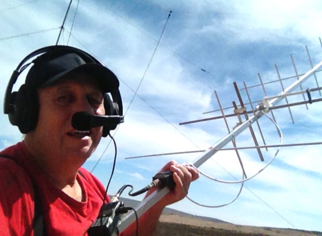 Construction of an antenna for experimental satellite communication, 8el. (435 Mhz) x 4el. (145 Mhz) Satellite Yagi crossed. No difficulty to built this antenna. Except the gamma match. that requires a little more attention
 -
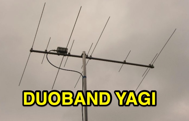 Duoband Yagi 2m/70cm with 4 Elements on 2 m and 5 Elements on 70 cm and one Feed point. The 4-El.-Ultralight-Yagi for 2m can be used on 70cm with an SWR of 1,5 without any changes.
 -
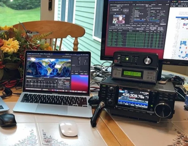 Explore the detailed setup, essential software, and operational nuances for Greencube (IO-117), a Medium Earth Orbit (MEO) satellite with a 70cm digipeater, offering DX possibilities for amateur radio enthusiasts. From antenna configurations to software choices, this guide covers everything for a successful Greencube experience.
 -
 Presents a detailed construction guide for a 9 dB, 70cm collinear antenna, utilizing readily available _RG58/U_ coaxial cable and PVC pipe for housing. The resource outlines the critical calculations for ½ wavelength sections at 444 MHz, incorporating the coaxial cable's velocity factor of 0.66, which yields a section length of 223 millimeters. It specifies the preparation and soldering of eight such half-wavelength sections, each cut to 231mm to allow for trimming, forming the core of the array. Further instructions detail the integration of a ¼ wave element (169mm #16 solid wire) at the top and a ¼ wave aluminum tube (160mm, 5/16 inch) at the bottom, crimped to the feed point's braid. The guide also addresses RF common mode current suppression by suggesting the use of _FT50-43_ toroids on the feedline. Final assembly steps cover mounting the antenna within ¾" PVC pipe using a wooden dowel, waterproofing connections, and initial SWR checks. The article also discusses scaling the design for different element counts and other VHF/UHF bands.
 -
 This article describes the construction of a simple dual-band VHF/UHF end-fed vertical dipole antenna designed for local repeater access using an Icom IC-705 radio. Built from a single piece of RG58U coaxial cable, the antenna consists of a 460mm exposed inner conductor, 450mm of intact coax, and a 9-turn choke balun wound on a 27mm former. Mounted on a 10m Spiderpole, the antenna achieves excellent SWR readings (<1.2:1 on 2m, <1.5:1 on 70cm) and provides effective coverage of local repeaters with unexpected reach into distant locations.
 -
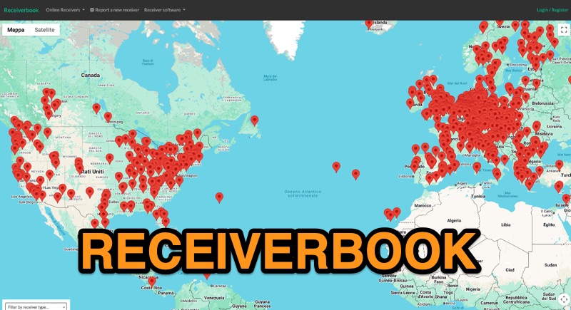 Monitoring radio communications through web-accessible Software Defined Radios (SDRs) has become a popular facet of the hobby, and Receiverbook serves as a centralized directory for locating these remote assets. The platform aggregates listings for both **OpenWebRX+** and **KiwiSDR** installations, providing a gateway to a diverse array of frequencies and operating modes. My own experience with similar directories highlights their utility for casual listening, DXing, and even troubleshooting local RFI by comparing signals across different geographic locations. The directory details specific receiver locations, from Bedford, England, to Marahau, New Zealand, and Berlin, Germany. Each entry often specifies the supported frequency ranges, which can span LF, MF, HF, VHF, and UHF bands, including dedicated segments like 80m, 40m, 2m, and 70cm. Many listings explicitly note support for HAM radio, broadcast services, and public two-way radio, making it a versatile tool for various listening interests. Beyond general frequency coverage, some entries provide granular details about the underlying hardware, such as the **SDRPlay RSP1A** or RTL-SDR Blog V3, and even the antenna types employed, like the Sirio Gain-Master. This level of detail is invaluable for serious SWLs and hams looking to understand the capabilities and limitations of a particular remote receiver before tuning in.
 -
 Amateur radio blog about Homebrew equipment,ham radio antennas, satellites, QO-100 operations, rf amplifiers, 2m ldmos amplifier, 70cm ldmos amplifier, 23cm ldmos amplifier
 -
 This is a plan for an optimized element UHF Yagi Antenna for UHF Bands featuring a 9dBd forward gain, a 13 dB front-back ratio, and a bandwith of 10 MHz on the 430-440MHz range.
 -
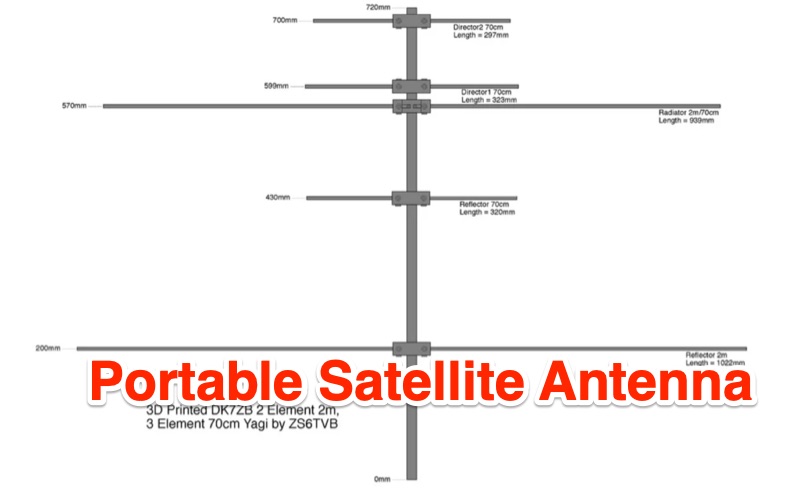 Demonstrates the construction of a portable dual-band Yagi antenna, specifically engineered for _full duplex_ satellite communication on the 2-meter and 70-centimeter amateur bands. The design adapts DK7ZB principles, utilizing tape measure elements for rapid deployment and 3D-printed brackets for structural integrity. It details element spacing, lengths, and the integration of a five-turn choke to mitigate common-mode currents, providing a practical solution for hams seeking a lightweight, self-built satellite antenna. The resource presents the antenna's performance characteristics, including a claimed gain of **4.1 dBd** for 2m and **6.2 dBd** for 70cm, achieved with two elements on 2m and three on 70cm. It contrasts this DIY approach with commercial alternatives, highlighting the cost-effectiveness of repurposing materials. The article includes design measurements and an image of the completed antenna, offering a tangible reference for replication.
 -
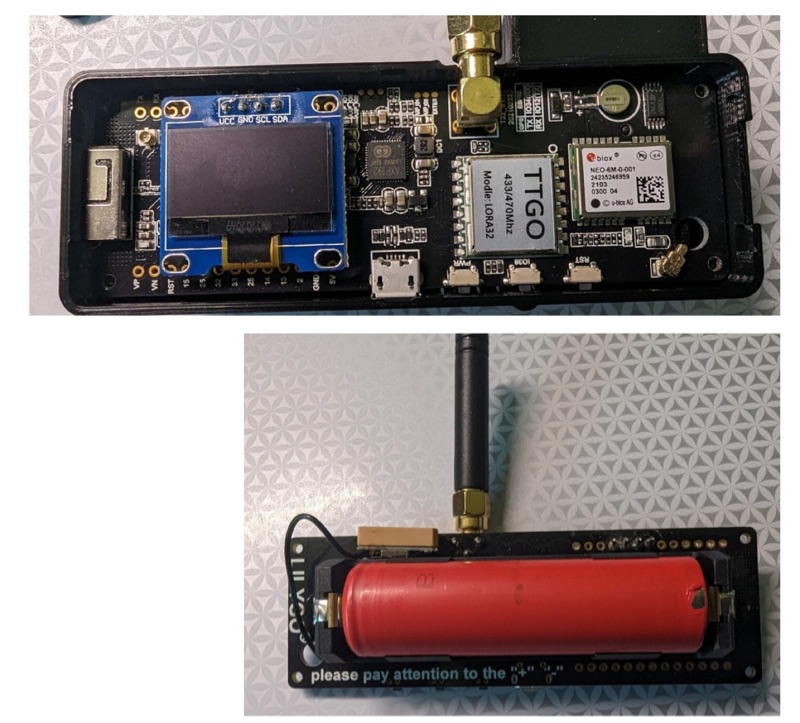 The resource details the construction of a 433 MHz LoRa APRS iGate and a tracker, both built around _TTGO T-Beam v1.1_ microcontroller boards. Each board integrates an OLED screen, WiFi, GPS, and an SMA antenna connector, powered by an 18650 3.7 V lithium-ion battery or microUSB. The iGate operates on 433.775 MHz, with its status verifiable on aprs.fi, demonstrating practical implementation of LoRa-based APRS solutions. The methodology involves programming the modules using Visual Studio Code with the PlatformIO plugin. This process loads the necessary firmware and a JSON configuration file, which includes the operator's callsign and WiFi credentials for the iGate. The guide emphasizes the ease of programming and provides specific steps for configuration. Initial testing of the iGate and tracker, including smart beaconing configuration, is documented. The low power output of approximately 200 mW from the LoRa board's transmitter is noted, with suggestions for range extension through improved antennas or RF amplification. The author, N4MI, plans to deploy a higher-gain 70cm antenna for the iGate.
 -
 The Pikes Peak Radio Amateur Association (PPRAA) serves as an ARRL Special Service Club, providing a calendar of events and activities for its members and the wider amateur radio community. The resource details upcoming events such as the USS Pueblo Memorial Museum Ships Weekend activations, a Cubical Quad Antenna Workshop, LARCFest, and various hamfests including Dayton Hamvention and Duke City Hamfest. It also lists on-air activities like a FreeDV digital voice mode event on 10 meters, a Black Friday Simplex Event on 2M and 70cm, and a 10m event for Technician class operators, emphasizing SSB privileges from 28.300 to 28.500 MHz. The PPRAA's event schedule includes educational opportunities like a Technician Class and a Soldering Workshop, alongside social gatherings such as the PPRAA Picnic and Car Show. Past event summaries highlight successful activities like the 2024 Megafest Raffle, Winter Field Day, and multiple fox hunts utilizing frequencies like 147.420, 147.480, and 147.540 MHz. The club actively supports POTA activations, exemplified by their AF0S park activation at Cheyenne Mountain State Park, and participates in historical commemorations like the USS Pueblo Memorial operations, demonstrating a broad engagement across various amateur radio facets.
 -
 The UHF J-Pole antenna described here utilizes an aluminum angle bar and 4mm galvanized threaded rod for its construction, with dimensions based on a previously published design. Assembly involves drilling the angle bar, securing threaded rod sections with nuts, and connecting the coaxial cable via cable lugs, ensuring the braid connects to the shorter element. ROS adjustment is achieved by manipulating nuts approximately **30mm** from the angle bar, allowing for fine-tuning of the impedance match. Once optimal tuning is established, _super glue_ is applied to seal the coaxial cable ends and protect the threaded rod cuts from corrosion, enhancing durability. This project emphasizes rapid realization with common hardware, providing a practical solution for radio amateurs seeking a simple yet effective antenna for the 70cm band.
 -
 Constructing a **J-Pole antenna** from 450 Ohm ladder line for 2-meter (144 MHz) and 70-centimeter (440 MHz) operation involves specific calculations and assembly steps. The design, based on an earlier KD6GLF concept using 300 Ohm twinlead, features a ¾ wavelength radiator and a ¼ wavelength matching stub, functioning as an end-fed half-wave antenna without requiring ground radials. It offers a gain of 2.4 dB over isotropic. The resource provides the formulas for determining the lengths of the ¾ wave radiator and ¼ wave stub, incorporating a velocity factor of 91% for 450 Ohm ladder line. For 146 MHz, the radiator measures 55 3/16 inches and the stub 18 3/8 inches. Construction details include cutting a 57¾-inch piece of ladder line, stripping 4 inches from one end, and attaching a 24-inch section of RG58 or RG8X coax with a 3-5 turn RF choke. SWR adjustment is achieved by sliding a shorting bar or by incrementally trimming the elements at a 1:3 ratio (stub to radiator). The goal is a 1:1.1 SWR at 146 MHz, which typically yields 1:1.2 at 446 MHz. The article also discusses power handling, noting that while 10-15 watts is fine, 50 watts may increase SWR to 1:2.1, and advises keeping the antenna away from other objects to prevent coupling and SWR degradation.
 -
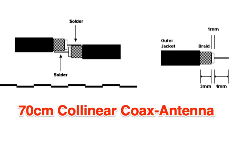 The 9 dB gain 70cm collinear antenna project details the construction of an 8-element array using RG58/U coaxial cable, designed for the 444 MHz band. Each half-wavelength section of RG58/U is precisely calculated, accounting for a velocity factor of 0.66, ensuring optimal resonance and performance. The design incorporates a quarter-wave wire element at the top and a quarter-wave aluminum or copper tube at the bottom, with specific length calculations provided for each component. Construction involves careful cutting and soldering of the coax elements, exposing the center conductor and braid, and tinning the braid for robust connections. The feed point connection to the main RG58/U coax is also thoroughly described, ensuring proper impedance matching for the UHF band. Encased in PVC pipe for weather protection, this homebrew antenna offers a cost-effective solution for amateur radio operators seeking a reliable UHF antenna. The article includes step-by-step instructions, making it accessible for those interested in building their own antennas.