Search results
Query: ladder
Links: 58 | Categories: 1
Categories
-
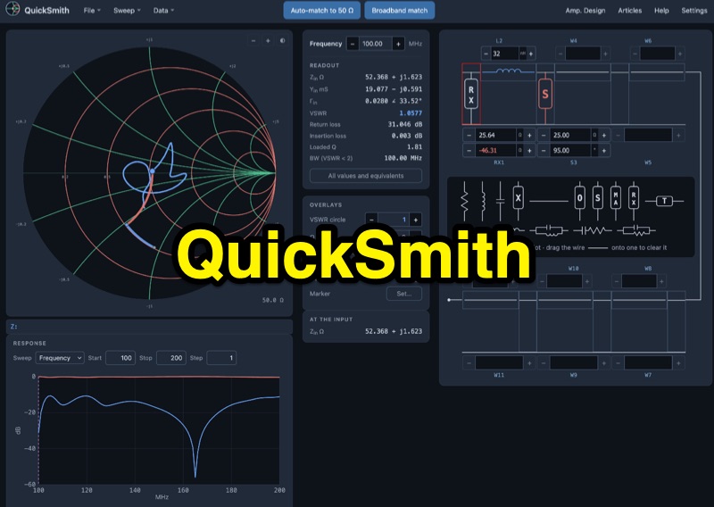 QuickSmith provides an online _Smith chart_ for impedance matching, enabling users to drag virtual components onto a ladder network and observe dynamic trace movement. The tool displays live readouts for critical parameters such as VSWR, return loss, insertion loss, loaded Q, and bandwidth. It facilitates auto-matching to **50 ohms** with various network choices and supports _Touchstone_ file import, allowing _NanoVNA_ measurements to be plotted directly for analysis. Beyond basic matching, QuickSmith includes features for frequency and component sweeps, generating S11 and S21 response graphs. It also supports amplifier design, incorporating stability, gain, and noise circles, alongside microstrip and coax synthesis capabilities. The platform offers shareable links, worked examples, and guided tours, making it a practical resource for hams learning about RF circuit analysis and antenna optimization.
-
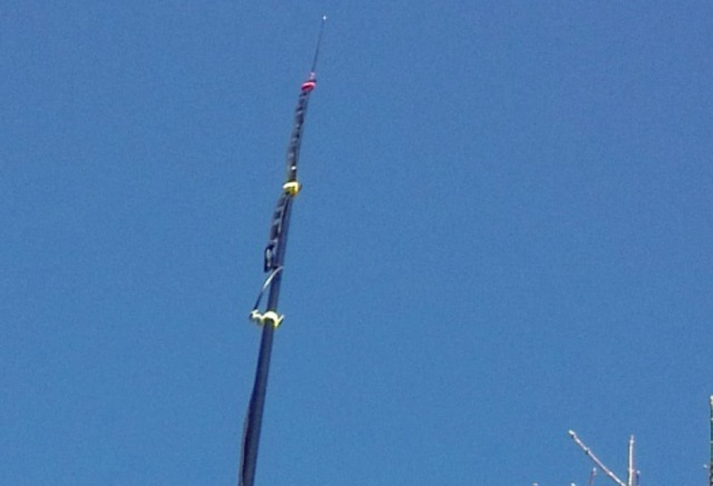 The Slim-Jim is a bit of a classic - building one is almost certainly a rite of passage and you will be glad that you did: It is easy to make, fairly easy to tune and rolls-up for transportation.
-
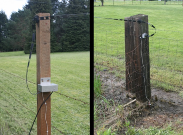 The Beverage we use is a DX Engineering RPS-1 dual directional 360 foot 109,7 m, oriented due North/South, six feet 1,8 m off the ground. The antenna uses 450 ohm ladder line as the antenna, and 75 ohm RG-6u for the feedline. The antenna runs atop the fence between our property and 5 acres of pasture next door.
-
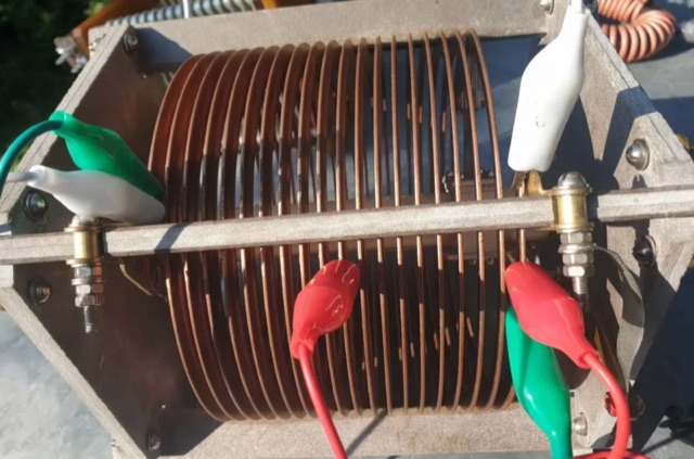 A transmitting antenna 2x15m, about 100 foot doublet antenna fed by a ladder line of about 600 Ohm. Article in Polish and English,
-
 This project describes the construction of a W3HH (T2FD) antenna for HF bands (3-30 MHz). While less efficient than a tuned dipole, it offers broad frequency coverage with a maximum SWR of 3.4 and reduces QRM (noise) significantly. On the 80-meter band, it shows slightly weaker signals than a dipole but with improved signal-to-noise ratio. The design includes non-inductive resistors, a 13:1 balun, and a "frog ladder" transmission line. Though not a high-performance antenna, it is compact and versatile, making it ideal for wide-band HF communication. Article in French
-
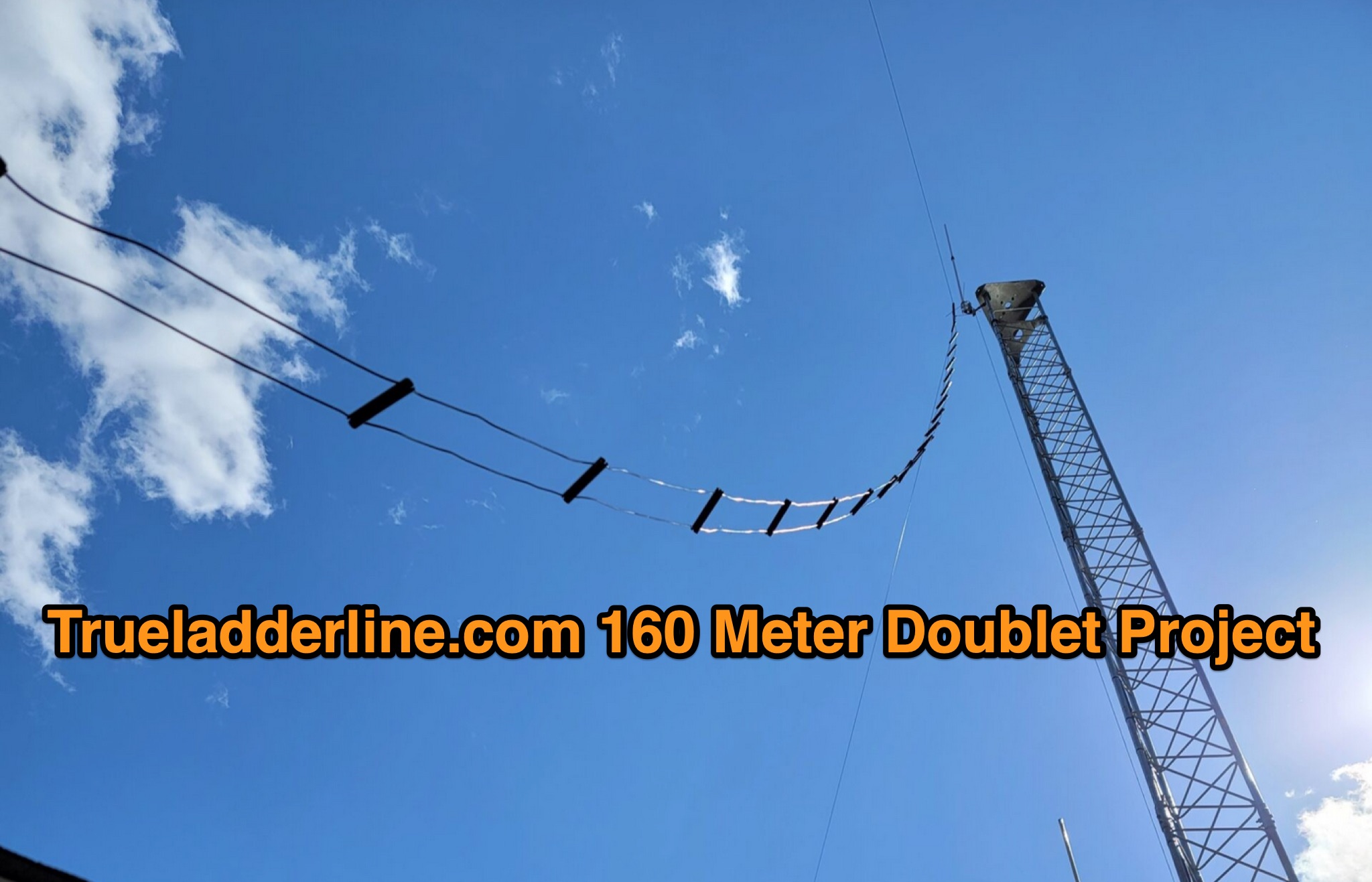 This page describes N6AQ's experience with a 160-meter doublet antenna from True Ladder Line. The operator initially attempted to install the antenna in a tree but later changed to a Rohn 45 tower for support. The antenna was upgraded to use 14ga wire instead of 16ga, and the performance was tested using an IC7300 transceiver with a 4:1 balun. Despite less than ideal setup conditions, the operator received positive signal reports on 40, 80, and 160 meters, thanks to advice from Gary at True Ladder Line.
-
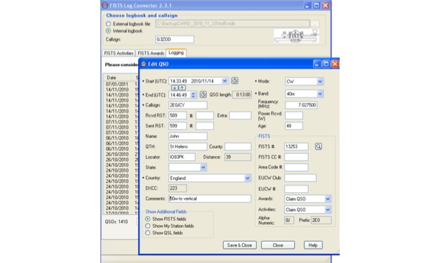 FISTS Log Converter simplifies various tasks for amateur radio operators. It aids in tracking FISTS Awards, submitting applications, and creating logs for FISTS Activities in Europe like the Ladder and EuCW Snakes & Ladders. Users can generate callsign checklists and import logs from existing logging programs via ADIF files. Available as freeware, it runs on Windows 2000 and later versions
-
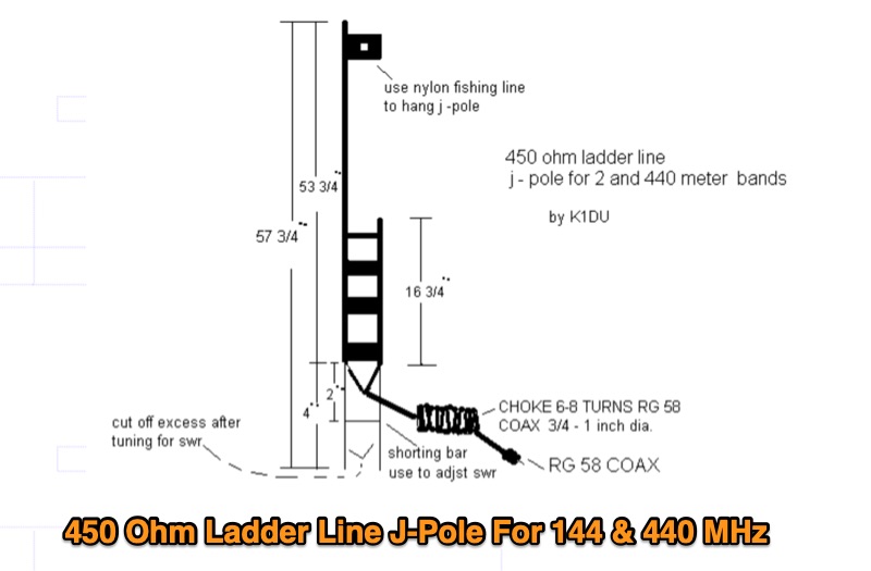 Constructing a **J-Pole antenna** from 450 Ohm ladder line for 2-meter (144 MHz) and 70-centimeter (440 MHz) operation involves specific calculations and assembly steps. The design, based on an earlier KD6GLF concept using 300 Ohm twinlead, features a ¾ wavelength radiator and a ¼ wavelength matching stub, functioning as an end-fed half-wave antenna without requiring ground radials. It offers a gain of 2.4 dB over isotropic. The resource provides the formulas for determining the lengths of the ¾ wave radiator and ¼ wave stub, incorporating a velocity factor of 91% for 450 Ohm ladder line. For 146 MHz, the radiator measures 55 3/16 inches and the stub 18 3/8 inches. Construction details include cutting a 57¾-inch piece of ladder line, stripping 4 inches from one end, and attaching a 24-inch section of RG58 or RG8X coax with a 3-5 turn RF choke. SWR adjustment is achieved by sliding a shorting bar or by incrementally trimming the elements at a 1:3 ratio (stub to radiator). The goal is a 1:1.1 SWR at 146 MHz, which typically yields 1:1.2 at 446 MHz. The article also discusses power handling, noting that while 10-15 watts is fine, 50 watts may increase SWR to 1:2.1, and advises keeping the antenna away from other objects to prevent coupling and SWR degradation.