Search results
Query: resonance
Links: 63 | Categories: 0
-
 This project explores the construction and performance of an Alford Loop antenna as an alternative to a round loop. The Alford Loop, symmetrically fed at opposite corners, behaves like a small loop despite its larger size. Built using PVC pipes and secured with tire wraps, the antenna integrates an LZ1AQ active amplifier for optimal performance. With deep nulls in its horizontal radiation pattern and improved resonance characteristics, this design has significantly outperformed previous active antennas in reception quality.
 -
 The article details the C-Pole antenna project, emphasizing its portability and ease of setup for amateur radio operators. Key features include its compact design as a vertical half-wave dipole that requires no radials, making it functional at various locations. The antenna employs capacitive loading to reduce physical length while maintaining efficiency. It includes practical advice on resonance tuning, impedance matching, and construction materials, along with a calculator for determining dimensions based on desired frequencies. Overall, it presents a user-friendly solution for portable ham radio communication.
 -
 A small magnetic loop antenna, often employed by hams facing antenna restrictions or high local RFI, offers a compact solution for HF operation. This resource details the construction of a foldable magnetic loop designed for the 40m through 17m bands, emphasizing its high-Q factor and _Faraday coupling_ for effective noise rejection and narrow-band filtering. The guide outlines material selection, advocating for copper over aluminum to maximize efficiency, and provides insights into the physics governing its operation, including impedance matching and resonance principles. Practical application of this antenna design is particularly beneficial for QRP enthusiasts and portable operators seeking a stealthy, high-performance antenna. The construction process includes specific details for a 1-meter diameter loop, a 140pF variable capacitor, and a _gamma match_ for impedance transformation. Performance comparisons suggest that while a full-size dipole might offer slightly better gain, the magnetic loop's ability to mitigate local noise often results in a superior signal-to-noise ratio, making it a viable option for challenging RF environments.
 -
 A half wave wire that is tuned for resonance on 80m will NOT be resonant on 40m despite a precise harmonic relationship between the two bands. The End Effect is caused by a capacitive coupling between an unterminated wire end and the ground.
 -
 This page delves into the debate surrounding the End-Fed Half-Wave (EFHW) antenna, exploring whether it is truly a multiband antenna without the need for a tuner. The author investigates the claims and criticisms surrounding these popular antennas, discussing their resonance on various bands and their efficiency for DXCC achievements. The content is valuable for hams interested in understanding the capabilities of EFHW antennas and their performance across different HF bands, with a focus on practical usage and real-world results.
 -
 Chokes and isolation transformers are essential for receiving antennas to mitigate common mode current, which induces noise and interferes with signal quality. Common mode chokes, formed by winding feedline through ferrite cores, block unwanted current effectively. Proper selection of core material and winding turns ensures resonance near the operating frequency, reducing interference. Isolation transformers further minimize interference, crucial for multi-transmitter stations.
 -
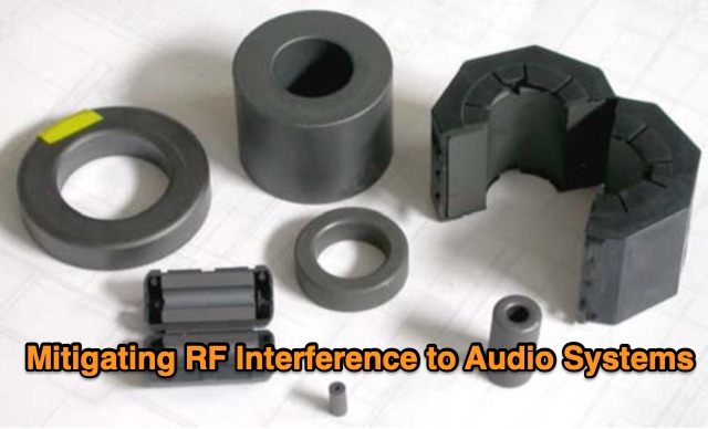 In this study, the author builds upon Muncy's research, demonstrating that radio-frequency current on cable shields affects audio systems through the "pin 1 problem" and shield-current-induced noise (SCIN). An enhanced equivalent circuit for ferrite chokes is proposed, addressing dimensional resonance and inductor self-resonance. Field tests confirm that chokes reduce interference across 500 kHz to 1,000 MHz. Guidelines for diagnosing and mitigating EMI from various sources are provided for product development and field installations.
 -
 The tri-band trapped delta loop antenna design operates on 80 meters (3.5–4 MHz), 40 meters (7–7.3 MHz), and 30 meters (10.1–10.15 MHz) using a single triangular wire loop. This configuration eliminates the need for an external antenna tuner or band-switching relays. The antenna's physical perimeter, approximately 270 feet, establishes 80M as the fundamental band, with specific trap placements enabling resonance on 40M and 30M. Trap design and placement are critical, with 30M traps positioned inboard of 40M traps within the horizontal element. Each slant leg measures approximately 80 feet. The resource references foundational information from the _ARRL Antenna Handbook_ and _ON4UN’s Low Band DXing_ regarding full-wave loop behavior and feedpoint impedances. The project aims to provide multi-band HF operation from a single, fixed antenna structure.
 -
 Delta loop antennas, particularly the 30 meter variant, offer unique advantages in terms of vertical polarization and omni-directional coverage. The construction process detailed by VE3VN highlights common mechanical and electrical challenges faced by amateur radio operators. Key design considerations include minimizing interaction with existing contest band antennas, achieving low elevation angles for DX chasing, and ensuring the antenna remains off the ground for agricultural clearance. The article provides specific measurements, such as the loop's height and feed point impedance, which are critical for optimizing performance. The use of NEC modeling software illustrates the importance of accurate resonance calculations, revealing how proximity to the tower affects both pattern and impedance. This practical account serves as a resource for hams looking to build effective antennas while navigating typical construction hurdles.
 -
 Demonstrates practical **rules of thumb** for selecting and utilizing ferrites and coils in amateur radio projects, particularly for RF applications up to 30 MHz. It addresses common challenges like determining appropriate ferrite grades and estimating L/C values without precise specifications. The resource details the author's experience with readily available grey ferrites, noting their suitability for HF work, and provides guidance on constructing **baluns** and RF chokes, balancing inductance for lower frequencies against inter-wire capacitance for higher frequencies. It also outlines a method for estimating power handling based on ferrite weight, suggesting a 1-gram ferrite can manage over 2 Watts, and offers a technique for evaluating unknown ferrites by winding 10 turns and measuring resonance with a 1 nF capacitor. This approach emphasizes a hands-on, iterative method for balun winding and adjustment, allowing operators to quickly approximate component values. The article compares the characteristics of ferrite-cored coils with air-cored coils, highlighting the reduced pickup and radiation of ferrite designs. It refines the air-coil estimation method for frequencies between 2.5 MHz and 10 MHz and provides a scaling factor for frequencies outside this range, aiming to get operators into the correct general area for their designs. The author's standardized ferrite choice (RND Components 165-00182) is presented as a practical example for reproducible projects.
 -
 This article explores the powerful features of AutoEZ as an Excel application working with EZNEC antenna modeling software. The article demonstrates how variables, equations, and formulas enable versatile antenna design and automatic optimization. Through practical examples including dipoles, inverted vees, delta loops, and monopoles, the author shows techniques for achieving resonance, implementing transmission line resonators for broadbanding, and optimizing antennas across frequency ranges. The step-by-step demonstrations cover unit conversion, coordinate calculations, segmentation considerations, and SWR optimization. This practical guide illustrates how AutoEZ extends EZNEC's capabilities, making complex antenna modeling more efficient and accessible.
 -
 A full-wave delta loop antenna, approximately 141 feet in total wire length for the 40-meter band, offers a low angle of radiation, which is highly advantageous for DX operations. This design, optimized for both 30m and 40m, leverages a specific circumference calculation of 1005/F, ensuring resonance on both bands through a simple switching mechanism. The antenna's configuration enhances long-distance communication, making it a practical choice for hams with limited space. The resource details the construction process, including the use of a _Ceramic Knife Switch_ for band selection and an _RG-11_ matching section to achieve optimal impedance. It outlines the precise loop lengths required for each band, along with tuning secrets to ensure efficient operation. Requiring a minimum height of 12 feet, this antenna can be supported by a single mast or tree limb, making it suitable for suburban installations where stealth or space constraints are a factor.
 -
 This page provides a detailed example of the modeling and analysis of an 80m delta dipole antenna with a 600-ohm bifilar feedline. The model is based on antennas used by the RAF from 1940 to 1970. It covers the original model specifications, conductor mass calculations, resonance frequency observation, geometry adjustment steps, and final antenna dimensions. The content includes theoretical formulas, resonance frequency calculations, and practical steps for adjusting the antenna for optimal performance. Overall, it serves as a practical guide for hams looking to understand and optimize the performance of a delta dipole antenna for the 80m band.