Search results
Query: 80 meters
Links: 227 | Categories: 2
Categories
-
 This article introduces an Arduino-based QRP CW Transceiver designed for lower HF bands. The journey begins with the Wotduino, evolving from a keyer to a multi-mode beacon. The development includes a QRP transmitter and culminates in a receiver inspired by Roy Lewallen design. The transceiver, controlled through a control bus features a signal path, modulation, filtering, and adjustable frequency settings. Despite initial testing intentions, successful QSOs on 80 and 40 meters showcase its functional capabilities.
 -
 This article documents the author's journey in building, modifying, and testing a DIY short vertical antenna for 40, 30, and 20 meters, with potential 80m capability. Initially inspired by Parks On The Air (POTA), the author explores pedestrian mobile operation and details various experiments to enhance antenna performance. The piece highlights challenges, SWR tuning, portability, and practical results, emphasizing a balance between efficiency and size. Ultimately, it showcases the adaptability of DIY antennas for portable ham radio applications.
 -
 WB8LZR details the construction and initial field results of a multi-band vertical wire antenna, designed to complement his existing horizontal loop for improved DX on 80 meters. The antenna utilizes a 67-foot vertical wire, configured as a quarter-wave radiator on 80m, and employs a 1:1 current balun for RF isolation on 80m, 30m, and 17m. For bands like 40m, 20m, and 10m, where the wire acts as a half-wave or full-wave radiator, an additional impedance transforming _unun_ is integrated to manage the significantly higher feedpoint impedance and voltage. The author notes the vertical's performance as a receiving antenna, observing reduced noise compared to his main horizontal loop, particularly on 80m, and even hearing some long-path signals the loop missed. Initial QRP contacts, including a **1-watt** QSO with a _VP2 station_ on 30m, demonstrate its transmit capability. While the radial system is currently rudimentary, the project outlines practical considerations for multi-band vertical deployment and impedance matching.
 -
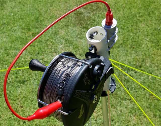 Experimentin wire antennas on top band using several type of aerials. This includes a 40 to 160 meters EndFed Half Wave kite antennas and 160m/80m loaded vertical antenna.
 -
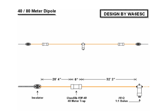 Make your own dipole for 40 and 80 meters band, assembling standard product parts like 40 meter traps, the 1:1 balun and insulators
 -
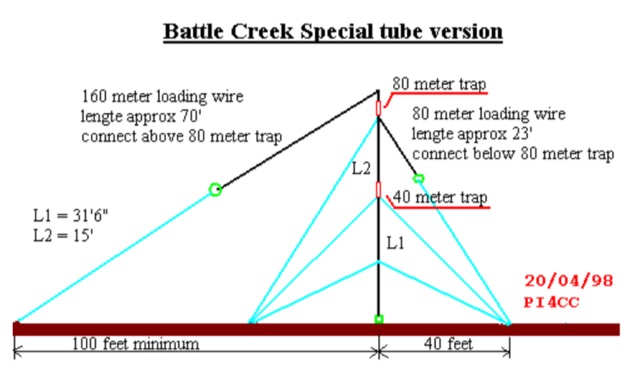 This antenna is designed for 40, 80 and 160 meters to complement a tri-band beam normally taken on DX peditions for 10, 15 and 20 meters, so six bands can be worked with only two antennas.
 -
 A CW contest running every Monday, from 1630 UTC to 1729 UTC on 40 and 80 meters band
 -
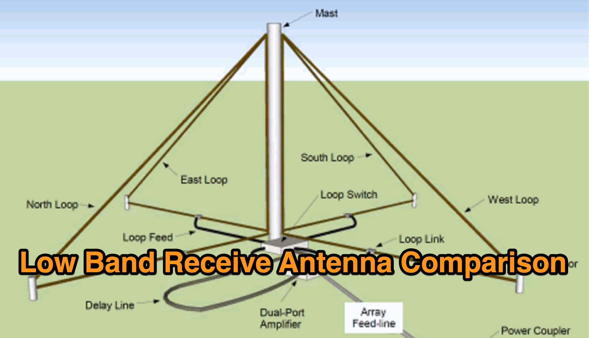 Discover the best low band receive antennas for hams with limited space. Learn about the K9AY loop antenna and Shared Apex Loop Array, two alternatives to the traditional Beverage antenna. Understand the concept of Relative Directivity Factor (RDF) and compare the performance of different receive antennas. See how the Shared Apex Loop, patented by Mark Bauman (KB7GF), offers an RDF between 8 and 10dB. Find out how to optimize antenna performance and enhance your receive capabilities on 160, 80, and 40 meters. Explore the world of low band receive antennas with insights from WB5NHL Ham Radio.
 -
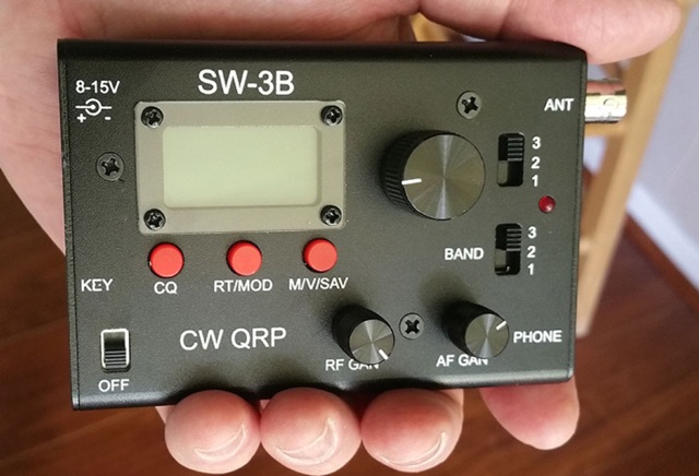 The SW-3B is a Three-band CW QRP transceiver, Weight 180g, output power 5W at 12v, 2W at 9v, works on 40 30 and 20 meters band
 -
 The tri-band trapped delta loop antenna design operates on 80 meters (3.5–4 MHz), 40 meters (7–7.3 MHz), and 30 meters (10.1–10.15 MHz) using a single triangular wire loop. This configuration eliminates the need for an external antenna tuner or band-switching relays. The antenna's physical perimeter, approximately 270 feet, establishes 80M as the fundamental band, with specific trap placements enabling resonance on 40M and 30M. Trap design and placement are critical, with 30M traps positioned inboard of 40M traps within the horizontal element. Each slant leg measures approximately 80 feet. The resource references foundational information from the _ARRL Antenna Handbook_ and _ON4UN’s Low Band DXing_ regarding full-wave loop behavior and feedpoint impedances. The project aims to provide multi-band HF operation from a single, fixed antenna structure.
 -
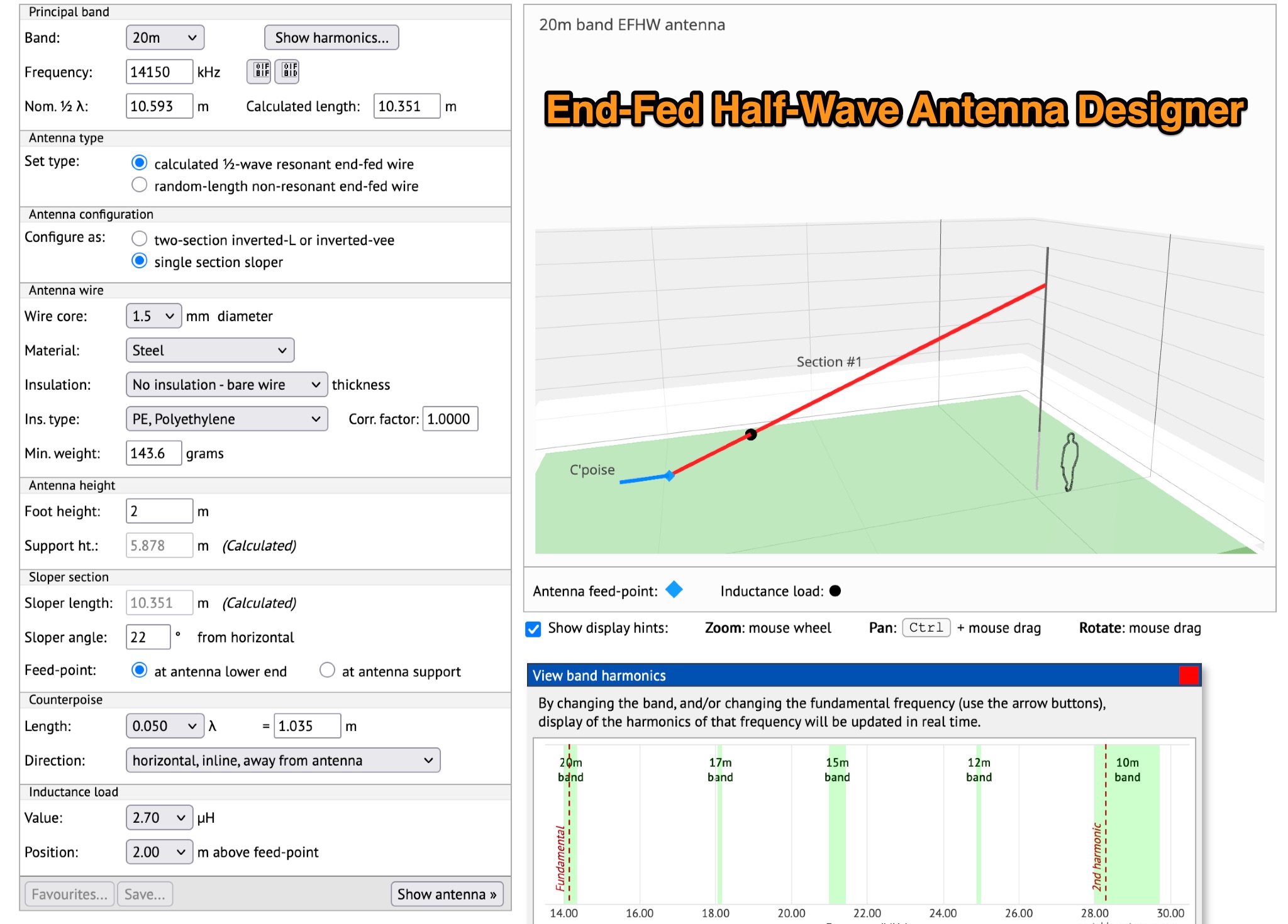 This page provides guidance on designing an End-Fed Half-Wave (EFHW) or Random-Length antenna for amateur HF bands, such as 80 or 40 meters. The content explains how to optimize the antenna for multi-band use and match it to a 50-ohm system using an unun. Hams can generate radiation patterns, VSWR charts, and antenna current diagrams for their customized antenna designs. Understanding how antenna dimensions affect performance is essential for successful field operations. The page caters to ham radio operators looking to build efficient and effective HF antennas for their stations.
 -
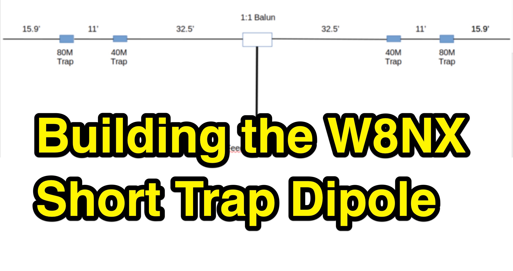 Learn how an experienced ham radio operator rebuilt his trap dipole antenna for 30, 40, and 80 meters after a storm damage. Discover the process of upgrading to a short trap dipole for 40, 80, and 160 meters using double-wound traps made from RG-58 coax. Follow along for construction details and tips on building this unique classi.
 -
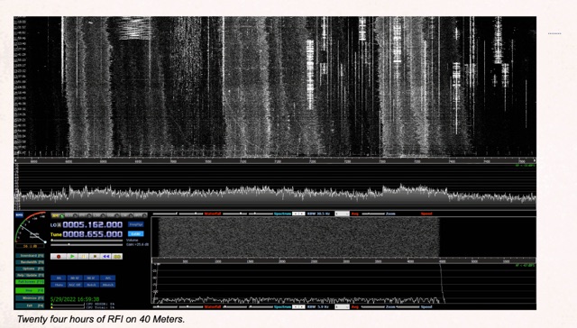 Demonstrates the application of Software-Defined Radios (SDRs) as effective tools for conducting Radio Frequency Interference (RFI) site surveys. The resource details the methodology for capturing and analyzing RFI, specifically focusing on the 80-meter band over a 24-hour period. It outlines the setup of an SDR-based survey tool, utilizing software like _S-Meter Lite_ and _Spectrum Lab_ to visualize and quantify noise sources. The article emphasizes the SDR's wideband capabilities, which allow for comprehensive identification and documentation of RFI across broad frequency ranges, crucial for effective mitigation strategies. The analysis presents practical results, illustrating how continuous monitoring can reveal intermittent RFI sources that might otherwise go undetected. For instance, the survey identified noise peaks exceeding **S9+20dB** on 80 meters during specific hours, correlating with local appliance usage. The methodology provides a repeatable process for hams to characterize their local noise floor, enabling targeted RFI suppression efforts and improving weak-signal reception, particularly for DXing and contesting.
 -
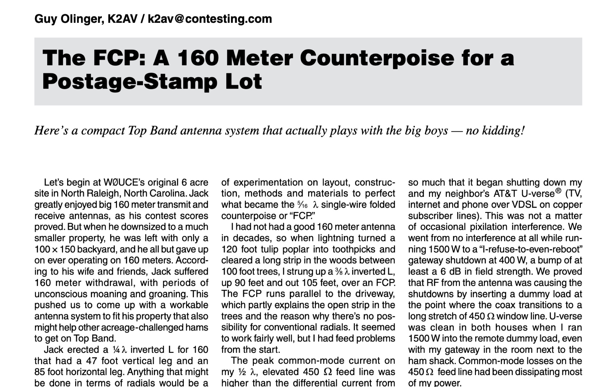 The article by Guy Olinger, K2AV, published in the May/June 2012 National Contest Journal, introduces the Folded Counterpoise (FCP), a compact 516-foot single-wire counterpoise elevated at 8 feet, designed for 160-meter operations on small lots like 100x150-foot backyards. Originating from efforts to revive Top Band for W0UCE on a postage-stamp property, the FCP uses strategic folds to cancel ground fields within 33 feet of center, minimizing losses to 0.13-0.53 dB—outperforming sparse or on-ground radials by up to 15 dB in poor soil—while mimicking opposed radials for efficient feedpoint impedance. Paired with a critical 1:1 or 4:1 isolation transformer (e.g., trifilar on T300-2 toroid) to block common-mode currents on coax feeds, it delivers proven results: K2AV's #8 North America low-power contest score, 7+ dB gains at W4KAZ and K5AF, and over 10,000 global web hits for DIY instructions using bare 12 AWG wire and weatherproof enclosures. Ideal for acreage-challenged hams, the FCP also excels on 80 meters with scaled dimensions, offering a low-loss alternative where full radials are impractical
 -
 This page provides information on how to design an Off-Center-Fed Dipole (OCFD) antenna, suitable for amateur HF bands like 80 meters or 40 meters. The antenna design allows for VSWR minima on multiple bands, making it a good choice for multi-band use. Learn how to create an OCFD antenna in either flat-top or inverted-Vee form using a single support. The page also offers tools to generate radiation patterns, VSWR charts, and antenna current diagrams for your specific antenna design, helping hams understand performance factors. Ideal for ham radio operators looking to build their own effective antennas.
 -
 Understanding radio wave propagation is fundamental for effective HF communication, and this guide from the Galway Radio Club elucidates the principles behind _Near Vertical Incidence Skywave_ (NVIS) operation. It begins by contrasting NVIS with line-of-sight and surface wave propagation, highlighting its utility for reliable regional coverage, particularly in challenging terrains or within the skip zone. The document explains how NVIS leverages high-angle radiation, refracting signals from the ionosphere to return to Earth within a circular region, typically up to **650 km** (400 miles) from the transmitter. The guide delves into critical factors influencing NVIS, such as the _critical frequency_ (Fo) and the Maximum Usable Frequency (MUF), emphasizing their dependence on solar activity, time of day, and season. It provides practical advice on frequency selection, noting that 40 meters is often the highest daytime NVIS band, with 60 meters and 80 meters favored as darkness falls. The author, EI5DD, suggests using an ionogram for real-time propagation data, considering it more reliable than generic ham-clocks. Antenna considerations are also covered, recommending dipoles, inverted vees, or phased dipoles positioned 0.1 to 0.25 wavelengths above ground for optimal high-angle radiation. The document mentions mobile NVIS setups, including military configurations and commercial options like the Barrett Communications roof-rack antenna, which can cost around **£2000.00**. It concludes by reinforcing NVIS as an essential technique for national emergency communications, with 5 MHz (60m) and 80 meters being primary bands for daytime and nighttime operations, respectively.
 -
 Details the installation and operation of the DX Engineering TFS Series Transmit Four Square System Phasing Units, specifically models like the DXE-TFS4-160B, DXE-TFS4-80B, and DXE-TFS4-40B. It covers system components, required parts, and a discussion of vertical antenna selection, including a table of suitable DX Engineering Monoband Vertical Antennas. Installation procedures are outlined, encompassing site selection, four square layout, topographical considerations, and noise source mitigation. Specific instructions are provided for mounting the phasing unit, antenna feedline connections using 1/4-wave 75-ohm coaxial cables, and control wire routing. The document also includes details on radial system implementation, with a table of radial wire lengths for 160, 80, 75, and 40 meters, and procedures for tuning the vertical antennas for optimal performance. Operational aspects of the Four Square Control Console are described, including front and rear panel functions, control logic (Table 4), and typical transceiver/amplifier interconnections. The system enables directional control with approximately 5 dB gain over a single vertical element in four directions or an omni-directional pattern, achieving typical front-to-back ratios exceeding 20 dB. Lightning protection and initial system testing are also addressed, along with a 5 kW CW and 10 kW PEP SSB power rating and hot switching lockout feature.
 -
 VE1ZAC's analysis details the performance of **MFJ927** and **SGC239** autotuners with portable HF vertical antennas, specifically comparing 31 ft and 43 ft configurations. The resource originated from challenges encountered during a Maritime QSO Party roving operation, necessitating a lightweight and easily deployable antenna system. Target bands for the contest included 80, 40, 20, 15, and 10 meters, with a maximum power handling of 100 W CW. The author utilized a 30-foot carbon fiber push-up pole to support a vertical wire element, noting its 2 lb weight and reliability. EZNEC modeling was employed to predict performance, showing favorable results for a 30-foot vertical with elevated radials, particularly on 40 and 20 meters. Feedpoint impedance measurements, taken with an AIM4170C, are presented for various HF bands, both with and without a 41-foot RG6 stub designed to reduce reactance on 80 and 20 meters. The stub significantly improved matching on these bands, easing the tuner's workload. Operational tests revealed issues with the MFJ927's reliability during contest setup, leading to reliance on the K3's internal tuner. The SGC239, tested post-contest, performed flawlessly. A detailed side-by-side comparison covers mechanical aspects, connection options, power bias, impedance range, board quality, and documentation. Modifications to the MFJ927, including a new aluminum case, white paint for heat reduction, and upgraded impedance-measuring resistors, are also described.
 -
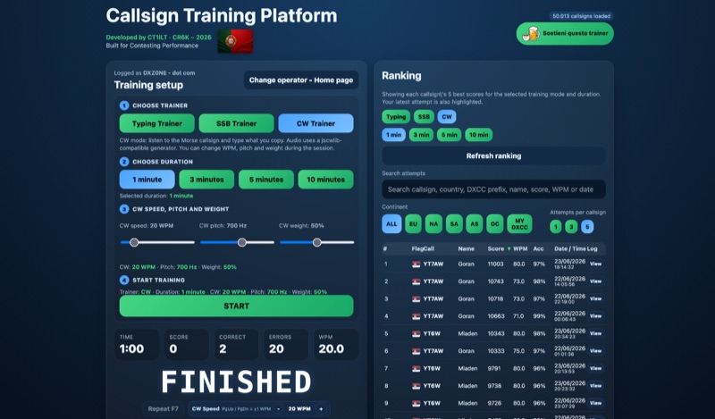 Improving callsign recognition and copying skills is fundamental for effective amateur radio operation, particularly in high-stress environments like contesting or DXing. The CW4EVER Callsign Training Platform provides a focused environment for operators to hone these abilities. It offers three distinct training modes: a Typing Trainer for visual recognition, an SSB Trainer for voice callsign practice, and a CW Trainer for Morse code proficiency, allowing users to tailor their practice to specific operational needs. Operators can select training durations of 1, 3, 5, or 10 minutes, providing flexibility for quick drills or extended practice sessions. For CW training, the platform allows granular control over parameters such as CW speed, adjustable up to **80 WPM**, pitch in Hz, and weight in percentage, enabling personalized learning curves. The system stores operator preferences locally and includes server-side anti-cheat protection, stricter callsign validation, and automatic score archives, ensuring fair competition and persistent training history. Recent enhancements include separate saved CW preferences per operator and _MY DXCC_ ranking positions. The platform also tracks global statistics, including total attempts worldwide, unique callsigns encountered, and total training hours logged, offering a broad perspective on user engagement and progress. These features collectively support operators in achieving higher accuracy and speed in callsign reception.
 -
 Presents DJ5IL's personal amateur radio station, detailing his journey as a licensed operator since 1973. The resource covers his **shack setup**, including an Elecraft K4D, Icom IC-7610, and various vintage transceivers like the Drake 2-B, along with a SPE Expert 1K-FA amplifier. Antenna systems include a PRO.SIS.TEL RD1524T rotary dipole for 40/20/15/10m at 15m height, an 18m vertical dipole with an SGC SG-230 tuner for 3.5-30 MHz, and an inverted-V dipole for 80m. The site features a **QSL gallery** showcasing his custom card designs and outlines his QSL policy, emphasizing the exchange of unique, personalized cards over generic confirmations. It also includes a detailed operator's biography, tracing his early fascination with radio, obtaining his license at 16, and memorable QSOs, such as a contact with his blood-relative W3NZ. The resource also delves into the historical significance of amateur radio's role in pioneering shortwave communication following the 1912 International Radiotelegraph Convention, which initially relegated amateurs to wavelengths of 200 meters and shorter. DJ5IL's philosophy on "ham spirit" is discussed, stressing the unpolitical nature of amateur radio as a global fraternity.
 -
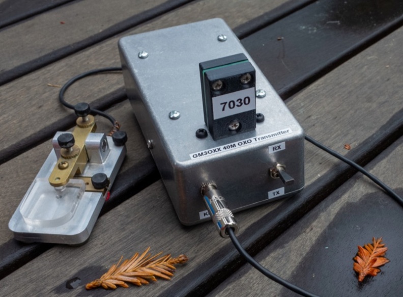 The project details the construction of a GM3OXX OXO transmitter, designed to accommodate **FT-243 crystals** using 3D-printed FX-243 holders from John KC9ON. It presents specific frequency adjustments, noting a 7030 KHz HC-49/s crystal could be tuned from 7029.8 KHz to 7031.7 KHz with an internal 45pF trimmer capacitor. The build incorporates a modified keying circuit to prevent oscillator run-on key-up and includes a TX/RX switch for sidetone via a connected receiver, with the transmitter output routed to a dummy load on receive. Practical construction aspects are thoroughly covered, including the process of cutting a rectangular opening in a diecast enclosure for the FT-243 socket and the selection of a **low-pass filter** (LPF) based on the QRP Labs kit, derived from the W3NQN design. The author achieved approximately 800mW output power from a 14.75V supply, measured with an NM0S QRPoMeter, using a 16.5-ohm emitter resistor in the 2N3866 final stage. The article also touches upon the potential for frequency agility across the 40M band using multiple FX-243 units with various crystals. The narrative includes a brief diversion into Bob W3BBO's recent homebrew projects, such as his Ugly Weekender MK II transceiver, highlighting the enduring appeal of classic QRP designs. The author reflects on the personal satisfaction derived from building RF-generating equipment, irrespective of DX achievements, and shares experiences of making local contacts with the 800mW OXO transmitter on 40 meters.
 -
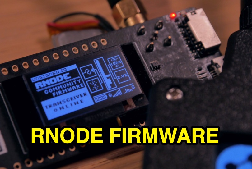 Enables digital radio transceivers to function as versatile data communication nodes, supporting applications like _Reticulum_ networking, messaging with Sideband, and acting as a LoRa-based KISS-compatible amateur radio TNC. This firmware transforms off-the-shelf development boards into powerful, long-range data radios, facilitating robust communication over significant distances, potentially achieving **hundreds of kilometers** with optimal setups. It supports a range of hardware, including unsigned.io's Handheld RNodes (v2.x and v1.x), LilyGO T-Beam v1.1, LilyGO LoRa32 (v2.0, v2.1), and Heltec LoRa32 v2 devices. Compatibility extends to transceiver modules utilizing Semtech SX1276, SX1278, SX1262, SX1268, and SX1280 chips, provided they have an SPI interface and exposed interrupt pins. Installation is streamlined via the `rnodeconf` utility, part of the `rns` package, simplifying the flashing process for users. The project operates under the GNU General Public License v3.0, promoting open development and user freedom. It encourages community involvement in building and deploying RNodes for various purposes, from personal communication to establishing resilient, decentralized networks. The firmware's design emphasizes flexibility, allowing for diverse configurations to suit specific operational requirements.
 -
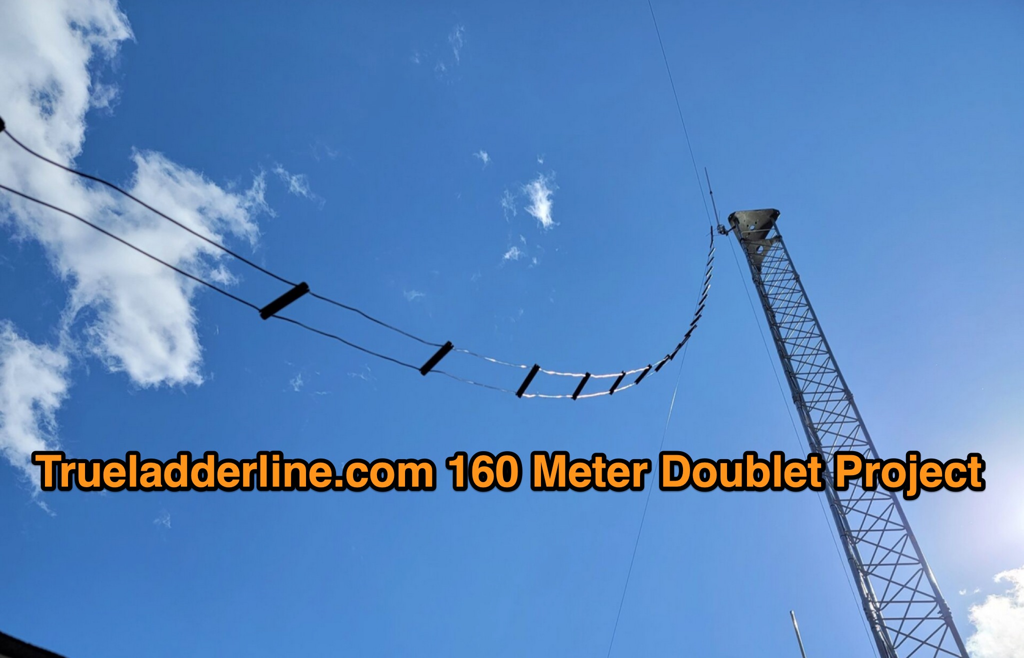 This page describes N6AQ's experience with a 160-meter doublet antenna from True Ladder Line. The operator initially attempted to install the antenna in a tree but later changed to a Rohn 45 tower for support. The antenna was upgraded to use 14ga wire instead of 16ga, and the performance was tested using an IC7300 transceiver with a 4:1 balun. Despite less than ideal setup conditions, the operator received positive signal reports on 40, 80, and 160 meters, thanks to advice from Gary at True Ladder Line.
 -
 A 5/8-wavelength vertical antenna for 2-meter FM operation is detailed, focusing on eliminating loading coils by utilizing a series inductor to cancel capacitive reactance at the feed point, thereby presenting a 50-ohm impedance match. The design illustrates three basic configurations, including a method employing a short-circuited coaxial stub for inductance, as implemented by K4LPQ. An alternative design is presented where the center conductor of the stub is extended one-quarter wavelength, creating a signal-frequency short and allowing for an insulated wire stub to develop the required series inductance. The article provides electrical theory and mechanical considerations for building the antenna, emphasizing the adjustment of stub length for proper impedance matching. This technical documentation is intended for amateur radio operators interested in homebrewing VHF antennas, offering practical insights into impedance matching techniques for vertical radiators.
 -
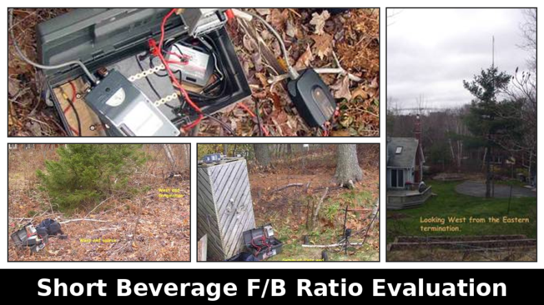 This resource presents a non-rigorous evaluation of the front-to-back (F/B) ratio of short Beverage antennas, specifically designed for low-band operation on frequencies such as 160, 80, 40, and 30 meters. The author, VE1ZAC, details the methodology used to measure the F/B ratio, which involves using a Millen Grid Dip Oscillator as a portable signal source. Measurements were taken by switching the antenna direction and recording S Meter and preamp readings to derive gain numbers. The document discusses the challenges faced in achieving accurate measurements and the assumptions made during the process, such as the calibration of S Meter units at 6 dB. This evaluation is particularly relevant for amateur radio operators interested in antenna performance on low bands.
 -
 Optimizing on-air audio for SSB, DXing, and contesting operations is addressed through a range of specialized audio processing equipment. The offerings include multi-band equalizers, specifically 5-band, 8-band, 10-band, and 12-band units, some integrated with features such as compressors, echo effects, noise gates, and phase rotation capabilities. These devices are engineered to interface with common amateur radio transceivers, with explicit compatibility noted for models like the Yaesu FT-DX10, FT-DX101D, FT-1000MP, FT-DX5000, Collins HF-380, and Flex 6300, alongside analog S/P meters for Icom rigs. The product line focuses on enhancing microphone audio characteristics, supporting XLR dynamic microphones for improved signal clarity and presence. The manufacturer, DB6QW Electronics, emphasizes direct support and a 100% manufacturer's warranty, reflecting confidence in product quality and operational reliability. This resource details specific audio processing tools designed to refine the transmitted audio signal, providing operators with granular control over their voice characteristics for competitive and casual amateur radio communications.
 -
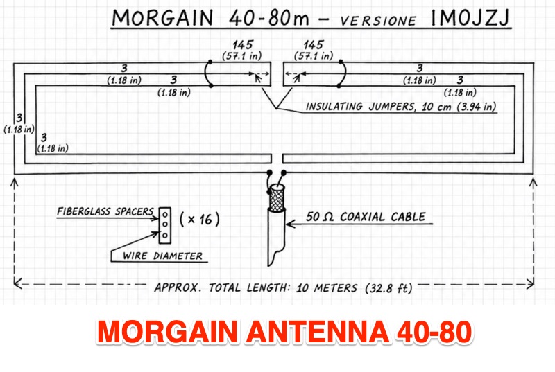 This resource details the construction and testing of a shortened Morgain dual-band wire antenna for 40 and 80 meters, designed for installations with limited space. The article, written by Remo - IM0JZJ, describes an alternative configuration that reduces the physical length of the antenna while maintaining its electrical design. It covers the author's testing process, including SWR measurements: 1.2:1 to 1.4:1 on 40 meters, and 1.1:1 to 1.5:1 on 80 meters (specifically 3620 kHz to 3720 kHz). The antenna has a feed-point impedance of approximately 50 ohms and requires a 1:1 current balun when fed with coaxial cable. The installation setup involved two 11.50-meter galvanized steel poles, supporting the antenna approximately 10 meters above ground. The completed antenna occupies about 10 x 0.5 meters and uses 64 meters of 1.5 mm2 insulated electrical wire. Tests were conducted from Sant'Antioco, southwest of Sardinia.