Search results
Query: power o
Links: 261 | Categories: 34
This query is too generic. Please try adding an additional term to focus your research.
Categories
- Shopping and Services > Alternative Power
- Manufacturers > Alternative Power
- Technical Reference > Alternative Power
- Manufacturers > Test Equipment > Power Meter
- Technical Reference > Power Meter
- Manufacturers > Power Supply
- Technical Reference > Power Supply
- Manufacturers > Accessories
- Radio Equipment > HF Amplifiers > Alpha 8410
- Radio Equipment > HF Amplifiers > Ameritron AL-80B
- Manufacturers > Amplifiers
- Shopping and Services > Batteries
- Technical Reference > Batteries
- Technical Reference > Radio Frequency Interference > BPL
- Manufacturers > Cable and Connectors
- Technical Reference > Dummy Loads
- Manufacturers > Lightning and Surge Protection
- Operating Modes > Lora and Mesh
- Radio Equipment > Antenna Tuners > MFJ-989C
- Software > Oscilloscope
- Technical Reference > Radio Frequency Interference > PLT
- Manufacturers > Alternative Power > Portable Generators
- Operating Modes > Portable Operations
- Operating Modes > QRP
- Ham Radio > Clubs > Technical Specialty > QRP Clubs
- Technical Reference > QRP Projects > QRP CW Transceiver
- Manufacturers > QRP Kits
- Technical Reference > QRP Projects
- Radio Equipment > VHF-UHF Amplifiers > RM VLA-200
- Manufacturers > Alternative Power > Solar Panels
-
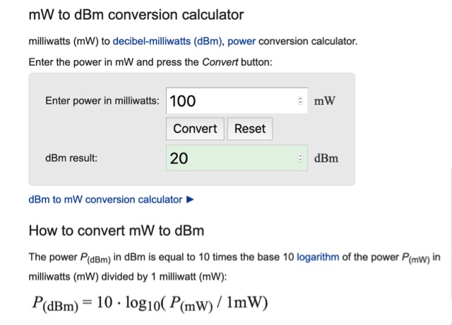 Online calculator that will convert power entered in milliwatts to dBm. Includes a quick mW to dBm conversion table
-
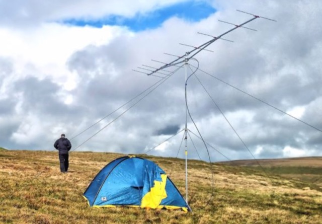 QRP is a way of operating that involves using low power transmitters, that are no more than 5 Watts for Morse or data modes, or 10 Watts pep for voice. Introduction to QRP operations
-
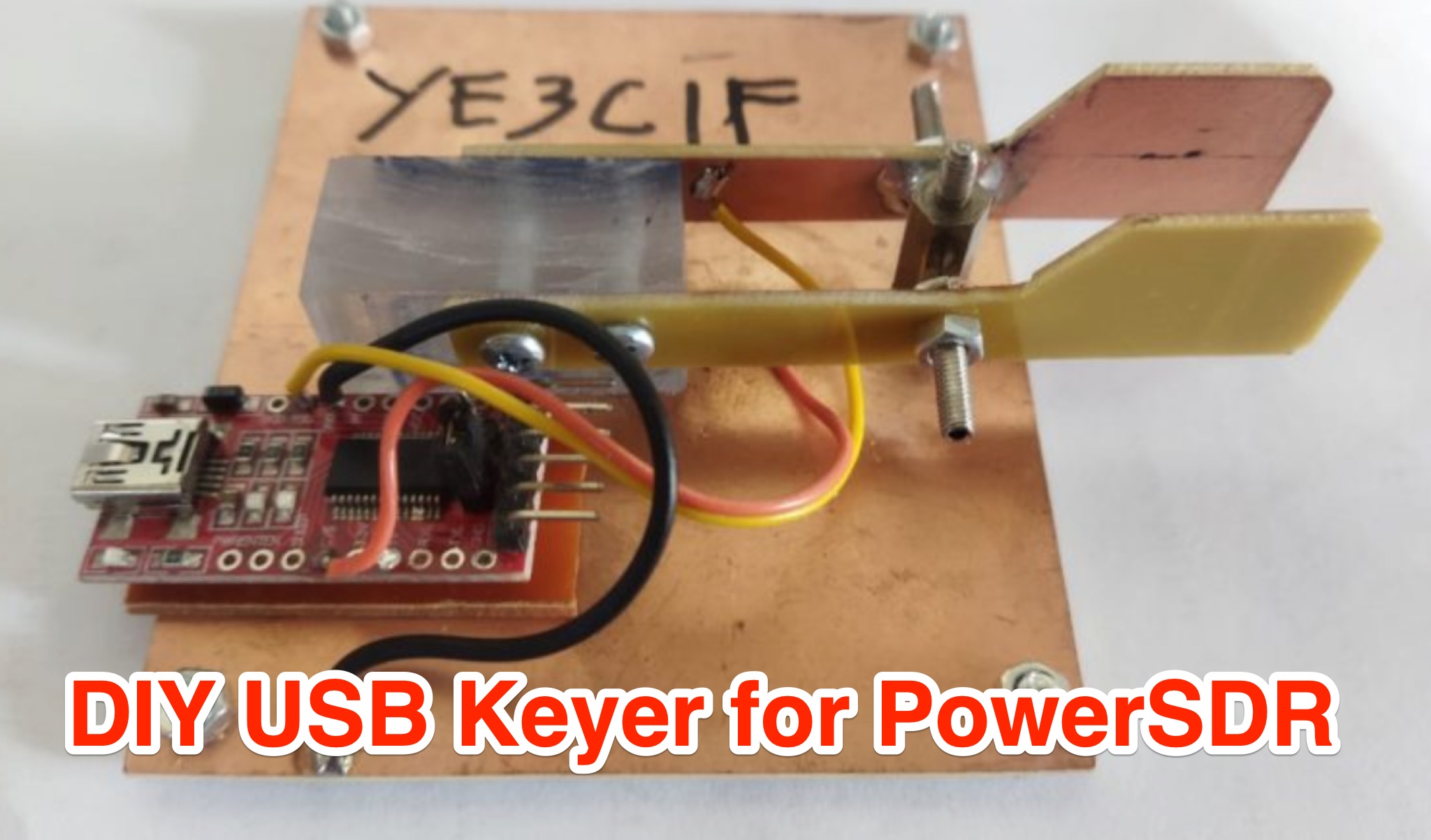 Learn how to create a USB Keyer for PowerSDR to enhance your CW experience. This article provides a step-by-step guide using affordable materials like a USB to TTL Module (FT232RTL) and a Keyer iambic. The tutorial includes a detailed wiring diagram and instructions for configuring the Keyer in the PowerSDR menu. The author also shares a helpful video demonstration to ensure smooth operation. Whether you're a seasoned ham operator or new to CW, this DIY project can improve your radio setup. Follow these instructions to build your USB Keyer and elevate your PowerSDR experience.
-
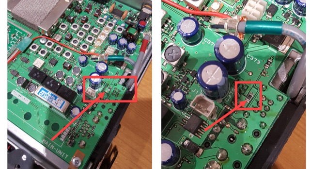 If your FT-817 has stopped powering up from the internal battery but works from external power, then maybe the internal battery fuse has blown. There is a small PCB mounted fuse to protect the battery and radio. This fuse can blow, if it does your radio will not work from battery power. This page will describe how to test the fuse and describe how to make a repair.
-
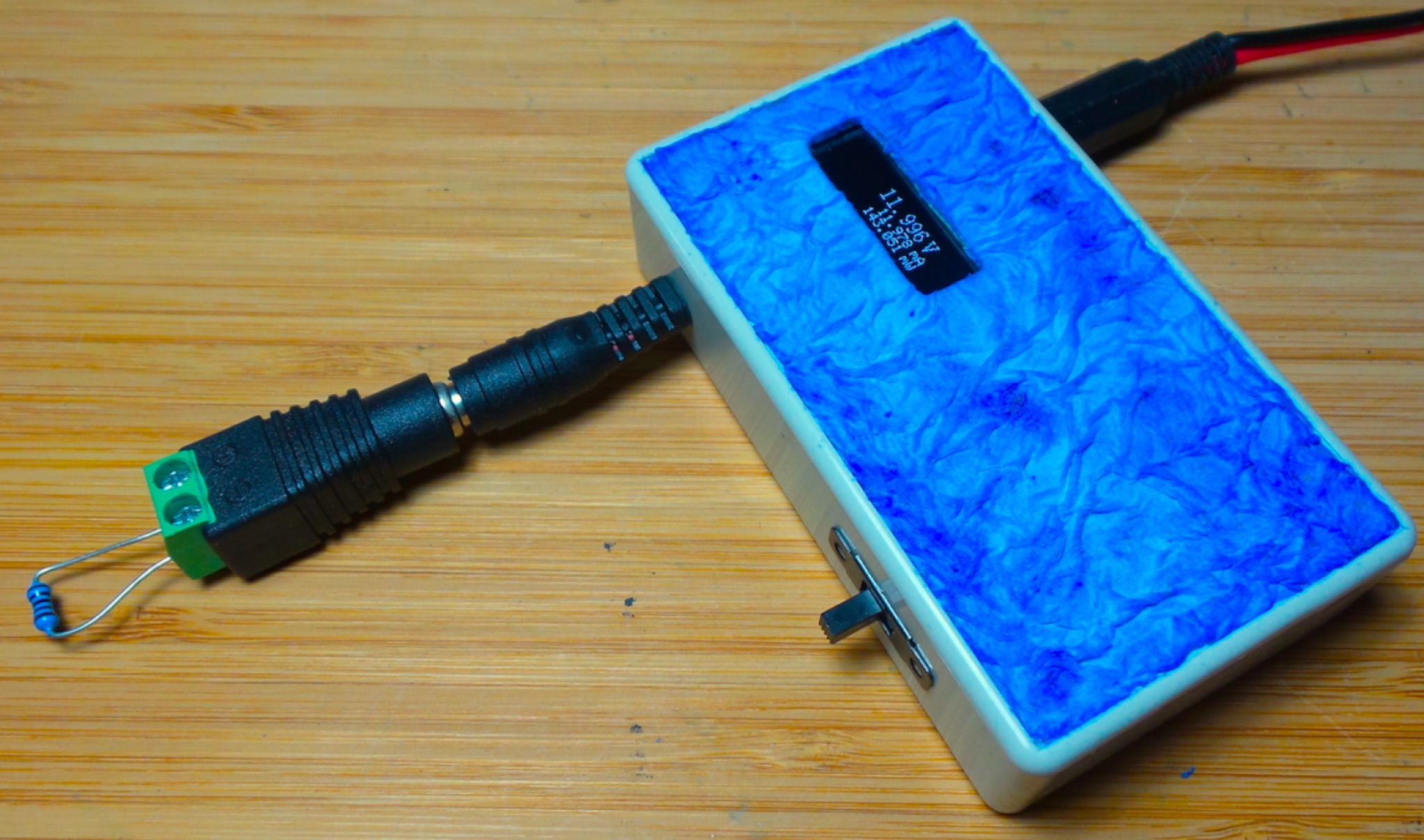 The DIY Power Meter project utilizes the _INA226_ high-side power monitoring chip, paired with an ATtiny85 microcontroller, to measure voltage, current, and power, displaying the results on a 128x32 OLED screen. The INA226 communicates via an I2C interface and is programmed with a calibration factor based on the shunt resistance and current register LSB. The project is designed to handle a maximum current of 500mA using a 0.16ohm shunt resistor, which can be adjusted to a 0.2ohm resistor, reducing the full-scale current range to 409mA with a resolution of **12.5uA**. The shunt resistor dissipates only 33mW at maximum current, making 1/4 watt resistors suitable for the setup. The PowerMeter.ino sketch configures the shunt resistance and maximum design current, automatically calculating the calibration factor. The project can be prototyped on a breadboard using an Arduino Uno, employing the Wire library for INA226 and OLED communication, and the u8g2lib library for the OLED display. For the ATtiny85 version, the Adafruit-TinyWireM and Tiny4kOLED libraries are used. The power meter is independently powered by a 3V CR2032 cell, with power switching options including manual switches or DC switched jacks. The low-side n-channel MOSFET switch configuration is tested but introduces voltage drop issues, making manual switching a more reliable option until a suitable DC switched jack is found. DXZone Technical Profile: INA226 | ATtiny85 | OLED Display | Power Meter
-
 This document provides a comprehensive guide on purchasing high-frequency (HF) high-power amplifiers, discussing key considerations such as new versus used models, tube versus solid-state technology, and troubleshooting common issues. It emphasizes the importance of understanding power needs for activities like DX chasing and contesting, alongside practical tips for selecting and maintaining amplifiers to ensure reliability and performance in various conditions.
-
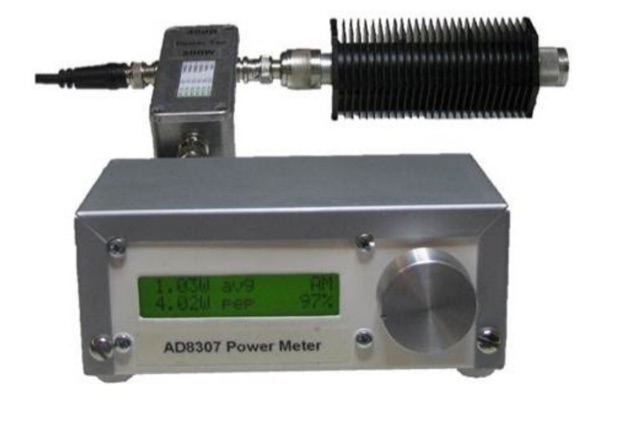 This project goal is to construct a versatile and informative RF power meter. The user-friendly interface, comprehensive power measurement capabilities, and AM detection function make it a valuable tool for various RF applications
-
 This excel workbook addresses the issue of power loss in transmission lines with complex characteristic impedance ZoZo​. It illustrates the discrepancy between actual loss (0.35 dB) and matched line loss (0.6 dB) using a simplified example, highlighting potential software tool limitations. The RF Feedline Power-Loss Calculator provides accurate end-to-end loss assessments for both microwave and RF applications. This tool is suitable for engineers and students and is compatible with Windows versions of Excel 2016 or later, though it is not compatible with Macintosh systems.
-
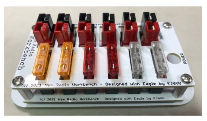 The **5-Port 12 Volt DC Power Strip Kit (Rev 4)** offers a practical solution for managing shack power distribution, providing one input and five fused outputs. All connections utilize the ubiquitous Anderson PowerPole connectors, a standard for many amateur radio operators, ensuring a clean, organized, and safe way to power multiple 12 VDC transceivers and accessories from a single source. This design mitigates the common issue of tangled wires and overloaded connections in a typical ham shack. Rated for a maximum current of 20 Amps at 12 VDC, the strip incorporates an integrated LED to indicate when external power is applied. Each output is individually fused, a critical safety feature that protects connected equipment from overcurrent conditions without affecting other devices on the strip. This level of protection is essential for preserving sensitive radio gear during operation. Assembly requires basic soldering skills and hand tools, with a high-power soldering iron and wide chisel tip specifically recommended for best results. The kit's compact dimensions of 4.13" x 1.78" allow for flexible mounting via screw holes, making it suitable for various shack configurations and portable operations.
-
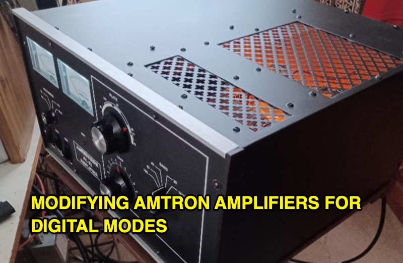 This resource details **cooling modifications** for Ameritron AL82, AL1200, and AL1500 HF amplifiers, specifically addressing heat issues encountered during high-duty-cycle digital mode operation. The author, WD4NGB, observed excessive heat in the tank area and band switch on an AL82, attributing it to insufficient exhaust over the 3-500 tubes and a complete lack of exhaust over the tank area. The modifications aim to prevent common failures such as damaged band switches and deformed insulating materials by increasing airflow and exhaust area. The page describes adding five holes to the chassis for enhanced cooling to the band switch and tank area, alongside enlarging the exhaust area over the inner 3-500 tube and the tank area on the amplifier cover, utilizing expanded metal for safety and RF shielding. The original cover featured 26.25 square inches of exhaust; the modified version significantly increases this to 48.5 square inches over the tubes and introduces an additional 15 square inches over the band switch. These changes are intended to resolve heating problems encountered during heavy, 100% duty cycle use in modes like RTTY or long SSB contests, which typically generate substantial heat. The article also discusses upgrading to a higher output fan, such as the G2E085-AA05-21, and modifying tube sockets for improved airflow and reduced back pressure, citing Tom Rauch (W8JI) of CTR Engineering as a source for parts.
-
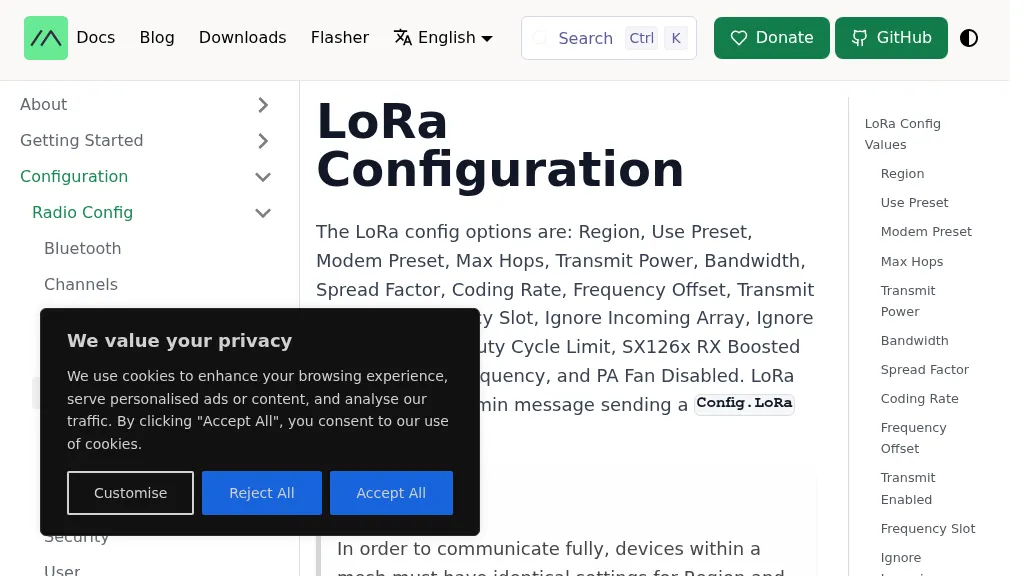 The Meshtastic documentation outlines critical LoRa configuration parameters for node operation, emphasizing regulatory compliance. It details settings such as Region, Modem Preset, Max Hops, Transmit Power, Bandwidth, Spread Factor, Coding Rate, and Frequency Offset. A comprehensive table provides region codes, frequency ranges (e.g., US **902.0 - 928.0 MHz**), duty cycles, and power limits (e.g., EU_433 **12 dBm**) for numerous countries, including the US, EU, China, and Japan, alongside a 2.4 GHz band option. It explicitly states that devices within a mesh must share identical _Region_ and _Modem Preset_ settings for full communication. Modem Presets, like _LONG_FAST_ (the default), optimize for either speed or range, directly impacting network congestion and message delivery delay. For instance, SHORT_TURBO offers the fastest speed and shortest range, while VERY_LONG_SLOW provides the longest range but is less reliable for mesh formation. The document also highlights specific duty cycle limitations, such as the 10% hourly limit for EU_433 and EU_868 regions, and provides command-line interface (CLI) examples for configuring these parameters.