Search results
Query: 20m 15m 10m
Links: 26 | Categories: 0
-
 A self-supporting vertical antenna design for stationary-mobile HF-VHF operation is presented, emphasizing ease of construction with common materials like a fiberglass fishing rod and PVC pipe. The design focuses on creating a set of no-tuner monoband radiators for bands such as **2m**, **6m**, 10m, and 12m, with an overall radiator support length of 3.3m. The construction process details the assembly of the antenna base using a magnetic mount, PL-259 connector, and PVC pipe sections, which then supports the telescopic fishing rod. Radiator extensions are cut to achieve quarter-wave resonance on specific bands, with detailed instructions for 6m (50-51 MHz), 10m (28.5 MHz), and 12m (24.9 MHz). For lower HF bands like 15m, 17m, and 20m, the design incorporates base-loading coils, with specific turn counts provided (e.g., 21 turns for 20m). The project also suggests using an _antenna analyzer_ for precise tuning of extensions and coils, moving beyond theoretical values to achieve optimal performance. The author, _IK1ZYW_, notes that for 80m and 160m, the antenna becomes less efficient as a vertical, suggesting alternative configurations like an inverted-V dipole or asymmetrical inverted-L.
 -
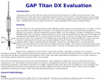 GAP Titan DX Evaluation, antenna for 10m 15m 20m 40m 80m
 -
 Multiband Center-Loaded Off-Center-Fed Dipole (CL-OCFD) antenna that work on 80m 40m 30m 20m 15m 10m. The Center-Loaded Off-Center-Fed Dipole (CL-OCFD) antenna, developed by Serge Stroobandt, offers a versatile solution for amateur radio enthusiasts, covering multiple HF bands (80, 40, 30, 20, 15, and 10 meters) without the need for an antenna tuner. This innovative design utilizes a capacitor for resonance on the 80-meter band and a resistor to manage static charges. The CL-OCFD enhances bandwidth and simplifies operation, making it a significant advancement on OCF Dipole design.
 -
 The ZS6BKW multiband HF antenna, a design by ZS6BKW (G0GSF), functions effectively on multiple HF bands without requiring an Antenna Tuning Unit (ATU) for 40, 20, 17, 12, 10, and 6 meters. This antenna, approximately **27.51 meters** (90 feet) long with a 12.2-meter (40-foot) open-wire feeder, is a direct descendant of the _G5RV_ but offers superior multi-band resonance. It can be deployed as a horizontal dipole or an inverted-vee, with the latter requiring only a single support and maintaining an apex angle of at least 90 degrees to prevent signal cancellation. Performance data, recorded with an MFJ Antenna Analyser, indicates SWR values of 1:1 on 7.00 MHz (40m) and 14.06 MHz (20m), with SWR below 1.3:1 on 17m, 10m, and 6m. While primarily designed for these bands, the antenna can be adapted for 80m, 30m, and 15m with an ATU, preferably at the balanced feeder's base. The use of 450-ohm twin-lead for the feeder is recommended over 300-ohm for improved strength and reduced losses, especially in adverse weather conditions. This design, originally published in _RadCom_ in 1993 and featured in Pat Hawker’s "Antenna Topics," provides a compact and efficient solution for HF operation, particularly for those with limited space or resources.
 -
 The **NW3Z** optimized wideband antenna designs, originally presented at Dayton 2001, detail Yagi configurations for the 20-meter, 15-meter, and 10-meter amateur radio bands. This resource provides access to the design files, likely containing critical parameters such as element spacing, element lengths, and boom dimensions, which are essential for replicating these directional antennas. The designs focus on achieving wide bandwidth, a desirable characteristic for contesters and DXers operating across a significant portion of each band. The content specifically references "nw3z-Antenna-DesignsDownload," indicating that the core information is available as a downloadable file, presumably in a format suitable for antenna modeling software or direct construction. Such files typically include **NEC models** or similar data, allowing for performance analysis and optimization before physical construction. The emphasis on "optimized wideband" suggests design considerations for SWR bandwidth and gain characteristics over a broader frequency range than typical narrow-band Yagis. The resource serves as a direct source for specific, proven antenna designs from a known amateur radio antenna designer, offering practical data for hams interested in building high-performance Yagi arrays for HF.
 -
 This wire-beam has one radiator-element, feeded with 450-Ohm-Wireman-twinlead and needs an antenna-tuner. For the bands 6m, 10m, 12m, 15m, 17m and 20m bended reflector-elements are used. The support is a cross of 4 fibreglass-fishing-rods
 -
 F6EZX presents a detailed account of constructing a compact, multi-band _Levy antenna_ for portable holiday operations, specifically addressing issues with local QRM from a previous _Deltaloop_ setup. The article outlines the design criteria, including multi-band operation on 40m, 30m, 17m, 15m, 12m, and 10m, a symmetrical configuration to reduce interference, and a low take-off angle for DX. Construction involves 2x 10.3m radiating elements and a 15.3m open-wire feeder (ladder line) with 7cm spacing, made from 1.5mm2 copper wire and foam pipe insulation spacers. Theoretical calculations, referencing F9HJ's "_Les antennes Levy_" book, guide the determination of element lengths and feeder impedance characteristics, aiming for a good match across bands with a commercial antenna tuner. Initial field tests with the _VCI Vectronics VC300DLP_ tuner showed a 1:1 SWR from 80m to 10m, with some difficulty on 17m. The antenna, mounted as a 45-degree slopper with the high point at 12m, successfully facilitated DX contacts to South America, particularly Chile and Argentina, suggesting a lower take-off angle compared to the previous Deltaloop which favored Brazil. The Levy antenna significantly reduced TVI/RFI, attributed to its improved symmetry and greater distance from the QRA. While signal reports on 15m and 20m were 1-2 S-points lower than the Deltaloop, its performance on 40m and 30m was comparable, fulfilling the design goals for a portable, low-cost, multi-band solution.
 -
 Constructing an HF End-Fed Half-Wave (EFHW) vertical antenna, the resource details the winding of a monoband matching unit, inspired by _AA5TB_, designed to provide a 50 Ohm impedance match without a ground plane or antenna tuner. It specifies the use of a _T200-2_ ferrite core for the transformer, outlining the 13-turn secondary and 2-turn primary winding process with enamelled copper wire. The document also describes the integration of a coax capacitor, whose length is critical for tuning and varies by band, with specific starting lengths provided for 20m, 17m, 15m, 12m, and 10m operation. The practical application section guides the builder through tuning the antenna using an antenna analyzer, emphasizing the iterative process of spacing secondary windings and trimming the coax capacitor to achieve resonance at the desired band frequency. It highlights the antenna's low angle of radiation, beneficial for DX, and claims up to 2 S-points improvement over a _G5RV_ or similar doublet when used as an omnidirectional vertical. A comprehensive shopping list, including specific part numbers from _Rapid Electronics_, is provided, along with advice on selecting fiberglass fishing poles for support and suitable antenna wire.
 -
 The 6 Band Inverted L Antenna MK3 is a versatile multiband antenna designed for amateur radio operators. This antenna covers 160m, 80m, 40m, 20m, 15m, and 10m bands, making it suitable for a wide range of HF communications. The design is based on a W3DZZ configuration, incorporating traps for optimal performance. The MK3 version features a sturdy 5/8th CB mast, replacing the original timber mast, which enhances durability against harsh weather conditions. The antenna's construction allows for effective operation, particularly on the 40m band, where it has been successfully used to contact distant locations including ZL, VK, and Antarctica. Constructing this antenna requires careful attention to detail, especially regarding the radials and grounding. The traps resonate at specific frequencies, and additional resources are available for building coaxial traps. The antenna is designed to work efficiently without an ATU on the lower bands, while higher bands may require tuning. This project is ideal for both beginner and intermediate operators looking to enhance their station with a reliable multiband antenna.
 -
 The Chameleon V1 HF Multiband Antenna is a mobile antenna that can also be used as portable. Lightweight mil whip antenna system with 10 BANDS capability 6m, 10m, 12m, 15m, 17m, 20m, 30m, 40m, 60m & 80m.
 -
 A simple beam antenna offering good performances on 3 bands by 9m2mso
 -
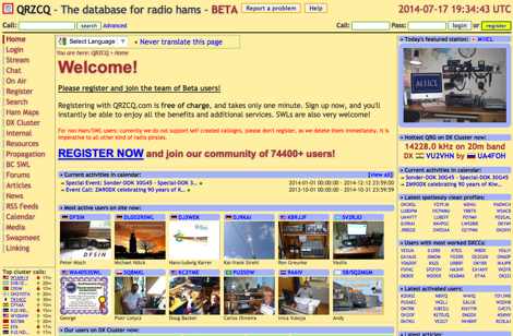 QRZCQ.com provides a centralized online platform for amateur radio operators, integrating a global callsign database with DX Cluster functionality. The service features real-time DX spotting, filtering capabilities for specific bands (e.g., 160m, 80m, 40m, 20m, 15m, 10m), and specialized filters for awards like IOTA, SOTA, WWFF, and QRP activity. It also includes a logbook, QSL manager lookup, contest calendar, and various ham radio articles and news feeds, supporting a wide range of operating activities and information retrieval. The platform aggregates data from multiple sources, offering a dynamic view of on-air activity and callsign information. Users can register for free to access additional services, including a personal logbook, buddy lists, and chat features, fostering community interaction among over 198,600 registered users. The DX Cluster displays recent spots with frequency, DX call, spotter, and remarks, covering bands from VLF to VHF. Beyond DX spotting, the site provides resources such as repeater directories, propagation information, and a swapmeet, making it a multi-faceted tool for both casual browsing and serious DXing or contesting. The service also highlights active users, latest news, articles, and videos, keeping the content fresh and relevant.
 -

-
 A simple 7 bands off-center dipole wire antenna designed to work on 80 meters band and that can cover also 40m 30m 20m 15m 12m 10m with acceptable SWR
 -
 The ZS6BKW antenna, a popular multiband wire antenna, offers improved band matching compared to the traditional G5RV. This construction guide details the process, beginning with specific dimensions: 13.11 meters (43 feet) for the 450-ohm ladder line and initial dipole arm lengths of approximately 14.8 meters each. It emphasizes the critical role of an _antenna analyzer_ for accurate tuning, particularly for determining the velocity factor of the ladder line and achieving a 1:1 impedance match. The article outlines the materials required, including a 1:1 current balun, 450-ohm window line, wire for the dipole arms, and a 50-ohm non-inductive resistor for testing. It provides a step-by-step procedure for cutting the ladder line to its electrical half-wavelength, explaining how to calculate the velocity factor using measured and free-space frequencies. For instance, a measured 50-ohm impedance at 12.54 MHz with a calculated free-space half-wavelength frequency of 11.44 MHz yields a velocity factor of 0.91. Final adjustments involve hoisting the antenna to its operational height and fine-tuning the dipole arm lengths to achieve optimal SWR, specifically targeting 14.200 MHz. The _ZS6BKW_ design is noted for its performance on 80m, 40m, 20m, 10m, and 6m, though it is not optimized for 15m operation. The author, _VK4MDX_, shares practical tips for durable construction using stainless steel wire and cable clamps.
 -
 Demonstrates the design and construction of a compact, portable multi-band mini-delta loop antenna, specifically optimized for /P (portable) operations from remote locations like Scottish islands. The resource covers the theoretical underpinnings of half-wave loops, contrasting closed and open configurations, and then details the application of a folded dipole principle to achieve a 50-ohm match for direct coax feed. It presents empirical formulas for calculating element lengths, considering the velocity factor of common wire types, and provides a detailed example for a 20m (14.175 MHz) version. The article includes a comprehensive table of dimensions and allowances for a five-band (20m, 17m, 15m, 12m, 10m) mini-delta beam, along with construction hints for the central support and balun. It specifies a 1:1 trifilar balun wound on a ferrite rod and describes the antenna adjustment process using an _MFJ-259B Antenna Analyser_. Initial test results indicate an SWR of 1:1 at resonance and a bandwidth of approximately 240 kHz on 20m, even at a low height of five feet above ground. The distinctive utility lies in its focus on a practical, easily deployable beam antenna for portable DXing, offering a viable alternative to more complex or larger arrays.
 -
 Over 100 amateur radio beacon audio files are presented, offering a direct auditory experience of propagation conditions across a wide spectrum of frequencies, from 1.8 MHz to 47 GHz. These recordings, primarily captured by IW3FZQ and IK3NWX, document signals from beacons such as DK0WCY, IY4M, GB3RAL, and S55ZRS, providing a valuable resource for **propagation study** and **beacon monitoring**. Each entry in the list specifies the beacon's callsign, its operating frequency in kHz, and the recording operator. This compilation includes signals from beacons located in various grid squares like JN55VF, JO44VQ, and IO91IN, illustrating diverse geographical origins. The frequencies covered span the 160m, 80m, 40m, 30m, 20m, 17m, 15m, 12m, 10m, 6m, 4m, 2m, 70cm, 23cm, 6cm, 3cm, 1.2cm, and 6mm amateur bands. Users can listen to these recordings to identify characteristic beacon tones and observe signal strength variations. The resource also invites other radio amateurs to contribute their own beacon audio files, fostering a collaborative archive of propagation data. The last update to this collection was on March 24, 2009, indicating a historical snapshot of beacon activity. Accessing the files requires the Real Player software.
 -
 Presents SWR analysis of an **Alpha-Delta DX-LB Plus** multiband wire antenna, installed as an inverted-V at 40 feet with ends at 15 feet, using an RigExpert AA-54 analyzer. The resource provides a full SWR sweep from 0.1 MHz to 54 MHz, followed by detailed SWR graphs for individual amateur bands including 160m, 80m, 40m, 30m, 20m, 17m, 15m, 12m, 10m, and 6m. The analysis highlights the narrow bandwidth on 80m and 160m due to loading coils, necessitating tuning for specific operating frequencies. It notes excellent SWR performance across the entire 40m band and good results on 10m, also requiring tuning. The author shares personal experience with the antenna, including a 17,000 km QSO on 20 meters, and discusses plans to replace it with a homebrewed parallel **fan-dipole**.
 -
 Covers 10m 12m 15m 17m 20m 30m 40m and 100 KHz on 80m, & WARC Eham Reviews
 -
 The CQ World Wide DX Contest records page details the highest scores achieved in the CQ WW DX Contest across various categories and years. It systematically lists records for both SSB and CW modes, segmenting results by entry class such as Multi-Multi, Multi-Two, Multi-Single High, Multi-Single Low, Single Operator High Power, Single Operator Low Power, Single Operator QRP, Single Operator Assisted High, Single Operator Assisted Low, and Single Operator Assisted QRP. Each record entry specifies the callsign, the operator's callsign in parentheses if different, the year of operation, and the total score achieved. The data is further broken down by individual amateur radio bands, including 160m, 80m, 40m, 20m, 15m, and 10m, allowing for granular analysis of performance within specific frequency segments. The page also includes records for the "ALL" band category, representing cumulative scores across all operational bands. The presented records span from 1948 to 2025, providing a historical perspective on contest performance. This resource also references other CQ contests like CQ WPX, CQ WW RTTY, CQ WPX RTTY, CQ 160, CQ VHF, and WW DIGI, indicating a broader context of contest record keeping. It explicitly states that late logs are not included in the records, ensuring data integrity. The page is maintained by the World Wide Radio Operators Foundation, Inc.
 -
 The CQ World Wide DX Contest records document top scores, with the Multi-Multi SSB category showing CN8WW achieving **78,170,508 points** in 2000. These records span from 1948 to 2025, categorizing results by region, operating class (e.g., Single Operator High Power, Low Power, QRP, Assisted), and specific bands like 10M, 15M, 20M, 40M, 80M, and 160M. For instance, EF8R (E77DX) holds the All-Band High Power SSB record with **25,747,775 points** in 2025. Each entry includes the callsign (with operator callsign in parentheses for guest ops), year of operation, and total score. The _CQ WW DX Contest_ also features records for the RTTY and VHF contests, alongside the main SSB and CW categories. QRP records demonstrate significant achievements, such as P40W (W2GD) with 5,097,780 points in the All-Band SSB QRP category in 2000. Multi-Two and Multi-Single categories are also detailed, providing a comprehensive overview of competitive performance.
 -
 Operating as FY/F5UII, Christian F5UII conducted a DXpedition to French Guiana (FY) from January 13 to 30, 2013. The primary operation utilized the FY5KE radio club station in Kourou, with activity focused on voice modes during specific weekday hours. The resource details the operator's intent to transmit before 12:00z and after 22:00z, or as availability permitted, from the mainland. A significant aspect of this operation involved a dedicated weekend activation of the Salut Islands, specifically **IOTA SA-020**, from January 19-20, 2013. This segment of the DXpedition was conducted from Royal Island (Ile Royale), part of a group including Devil's Island (Ile du Diable) and St. Joseph Island (Ile Saint Joseph), located 14 km offshore from Kourou. The station setup for the IOTA activation included 100 Watts of power, a GPA-030 vertical antenna for 10m, 15m, and 20m, and dipole antennas for 17m and 40m, with antenna deployment contingent on site conditions and propagation. The operator anticipated strong interest for the SA-020 entity.
 -
 This study details a reception comparison between vertical and horizontal active loop antennas, specifically two identical _Wellgood active loop antennas_, on various HF bands. The experiment, conducted in a densely populated QRM-prone area, monitored FT8 signals over a 24-hour period using two identical receivers. The methodology involved direct comparison of signal reception across the HF spectrum, aiming to identify performance differences based on antenna orientation. The results indicate that vertical loops demonstrated superior performance on higher bands (10m, 15m, 20m), while horizontal loops excelled on lower bands (30m, 40m, 160m), particularly for receiving long-distance (DX) signals. The horizontal loop's advantage on lower bands is attributed to potentially better low-angle performance and reduced sensitivity to man-made noise, yielding a **2-3 S-unit** improvement on 160m. The study provides practical insights for optimizing antenna placement in challenging urban environments, noting that the horizontal loop consistently showed a **10-15 dB** signal-to-noise ratio improvement on lower bands.
 -
 The Shrunken Quad antenna is a unique design that offers full-sized performance on the 10m and 15m bands while incorporating linear loading via a trap for operation on the 20m band. This design allows for effective communication in the HF spectrum, making it suitable for both casual operators and serious DXers. The quad configuration provides excellent gain and directivity, which is beneficial for contesting and long-distance contacts. Constructing the Shrunken Quad involves careful attention to dimensions and materials to ensure optimal performance. The antenna's compact nature makes it an excellent choice for limited space situations, allowing operators to enjoy the benefits of a quad without the need for extensive real estate. This project is ideal for amateur radio enthusiasts looking to enhance their station's capabilities with a versatile and efficient antenna system.
 -
 This project details the design and construction of a Spider Quad antenna for HF bands (20m, 17m, 15m, 12m, and 10m). The boomless structure optimizes driver and reflector spacing, enhancing performance. Tuning and impedance matching were refined using antenna analyzers and a 1:2 balun. Final tests confirmed excellent SWR and gain, making this an efficient solution for top performance DXing.
 -
 Presents detailed expedition charts and statistics for the **XX9W** DXpedition, covering operating time, total QSOs, unique calls, and duplicate QSOs. The resource provides comprehensive band and mode breakdowns, including FT8, SSB, CW, and FM, across 80m, 40m, 30m, 20m, 17m, 15m, 12m, 10m, 6m, 2m, and 70cm. Users can access DXCC statistics by band and mode, daily QSO totals, and multiband QSO statistics. Continent-by-mode and continent-by-band breakdowns are also available, detailing activity from Africa, Asia, Europe, North America, Oceania, and South America. The platform also tracks the expedition's impact on user totals, showing new band, new mode, new band + new mode, new slot, and new DXCC contacts.