Search results
Query: circuit drawing
Links: 8 | Categories: 0
-
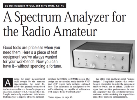 Demonstrates the construction of a **homebrew spectrum analyzer** designed by Wes Hayward, W7ZOI, and Terry White, K7TAU, enabling radio amateurs to build a capable test instrument without significant expense. The resource details a _double-conversion superheterodyne_ circuit, employing intermediate frequencies of 110 MHz and 10 MHz, and covers essential blocks such as the time base, logarithmic amplifier, resolution filters, and local oscillators. It highlights the use of hybrid and monolithic ICs, including mixers, amplifiers, and VCOs, to simplify construction while maintaining performance. The design supports useful measurements in the 50 kHz to 70 MHz range, with methods outlined for extending capabilities into VHF and UHF. The authors emphasize that this analyzer, while simple to build, is intended for serious measurements, requiring careful control of signal levels to avoid spurious responses. It uses an oscilloscope for display, with specific instructions for calibration and adjustment of various stages, including the log amplifier and IF gain. The guide provides detailed schematics and component lists for each section, such as the 110 MHz triple-tuned band-pass filter, which achieved **90 dB** image rejection, a significant improvement over double-tuned circuits. Practical advice on alignment and troubleshooting is included, drawing on the authors' extensive experience in RF circuit design.
 -
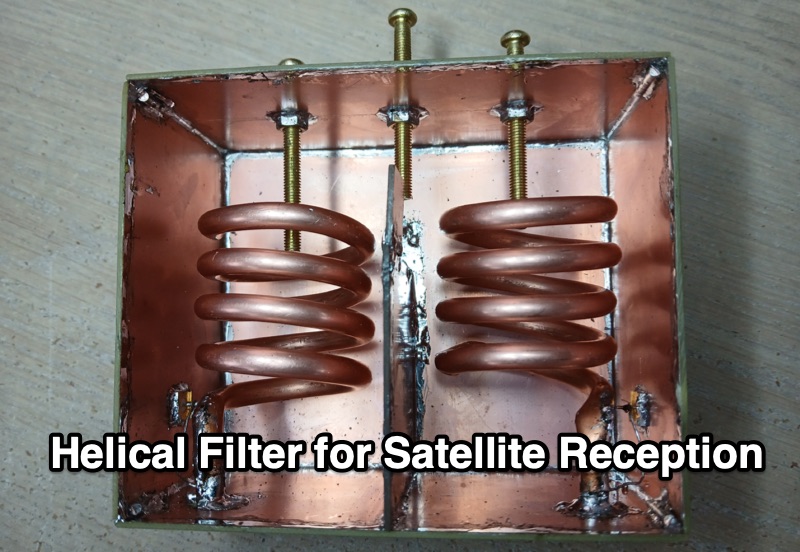 VE3NEA presents a detailed account of designing and constructing a **helical filter** specifically for 144 MHz satellite reception, addressing severe SDR receiver overloading from nearby Land Mobile Radio Network signals between 141 MHz and 143 MHz. The author's experience with RTL-SDR, RSP1a, and Airspy Mini receivers demonstrated the necessity of a narrowband solution to enable reception in the 145.8-146 MHz range with only 3 MHz separation from strong interference. The resource delves into the theoretical underpinnings of helical resonators, drawing upon Anatol I. Zverev's "Handbook of filter synthesis." It explains the equivalent circuit of a two-resonator passband filter, highlighting the critical role of stray capacitance (C3) in determining the coupling coefficient (K) and emphasizing the importance of **critical coupling** (K=1) for optimal filter performance. Misconceptions regarding tap positions and impedance transformation are clarified, with tap placement shown to control resonator loading and the trade-off between bandwidth and losses. Construction details include sourcing materials like 1/4" copper tubing and PCB, precise assembly techniques, and the use of tuning screws for frequency and coupling adjustments. Measurements performed with a NanoVNA revealed discrepancies from initial Coil64 calculations, necessitating adjustments to helix turns and tap positions to achieve the desired 3.5 dB passband loss and 40-50 dB suppression of interference.
 -
 The W6JWS 2-meter Repeater Maintenance and Repair Log documents the ongoing upkeep of a 146.745 MHz repeater, specifically addressing modifications to enhance its functionality. It details changes made to ensure the repeater powers up in _PL mode_ and to improve the reliability of touch-tone control, drawing comparisons to similar work performed on the AE6KE repeater. The log also notes a repair to a fused wire in the reverse battery protection circuit after an accidental polarity reversal, highlighting a temporary workaround where a wire was omitted but the system remained operational. The resource includes practical insights from Jeff Liebermann, AE6KS, regarding jumper configurations and programming, with accompanying photos. It provides access to several documents for the Icom RP-1510 repeater, including operating manuals and a schematic for the single logic board version, which differs from the dual-board configuration described in some printed manuals. The log mentions a specific modification to adjust the dropout delay, which was later deemed unnecessary, and references a related project for the AE6KE repeater, aiming to replicate successful modifications on the W6JWS machine, resulting in improved touch-tone reliability and proper PL mode activation.
 -
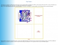 Amateur Packet Reporting System (APRS) operations often require compact, reliable solutions for transmitting position data, particularly for mobile or portable stations. This resource details the construction of the _Tiny Track-I_, a transmit-only APRS tracker designed for straightforward integration with a VHF radio and a Global Positioning System (GPS) receiver. It enables hams to broadcast their location without the complexity of a full-duplex TNC. The project outlines the printed circuit board (PCB) layout and schematic, based on an original design by N6BG, with a personal PCB drawing by SV1BSX. It includes specific component placement and notes an additional 10uF/10V capacitor (C5) for improved IC voltage decoupling, a modification not present in the original N6BG diagram. The unit connects to a computer or GPS via a DB9 female connector. This tracker is ideal for basic position reporting, offering a simple and effective way to participate in APRS networks. Its small footprint makes it suitable for vehicle installations or field deployments where space is limited, providing a **reliable 9600 baud** data stream for location updates.
 -
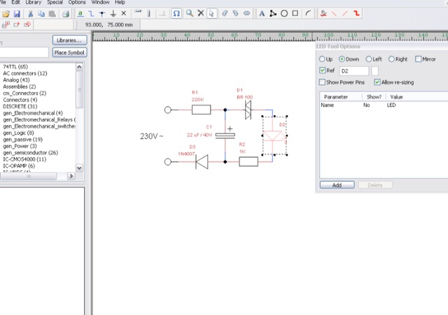 TinyCAD is a an open source program for drawing circuit diagrams which runs under Windows. TinyCAD is a program for drawing electrical circuit diagrams commonly known as schematic drawings. It supports standard and custom symbol libraries. It supports PCB layout programs with several netlist formats and can also produce SPICE simulation netlists.
 -
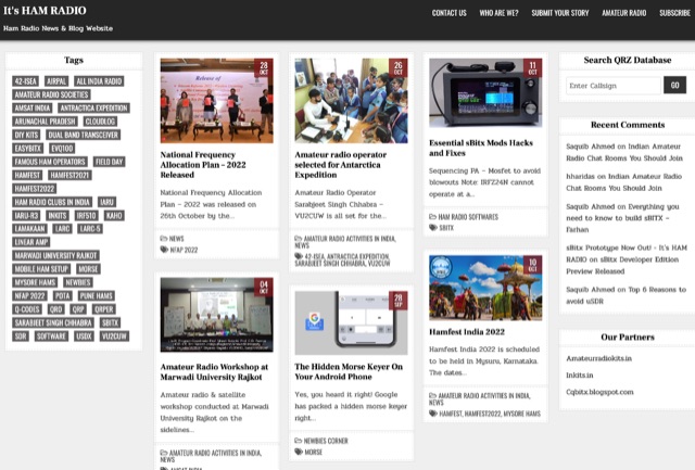 Focusing on the Indian amateur radio community, this resource provides a collection of articles covering news, technical tutorials, and DIY project instructions. It features content on various aspects of ham radio, including club activities, circuit ideas, and general information relevant to operators in India, often referencing local events and regulations. The site serves as a central point for information exchange within the region. The author, VU3HZW, shares insights and practical guidance, drawing from personal experience to present topics such as antenna construction and station setup. The content aims to support both new and experienced hams, with articles detailing specific projects and offering practical advice for improving station performance or engaging in local ham radio activities. For instance, one article might detail a simple _QRP transceiver_ build, while another could discuss optimal antenna placement for **local nets**.
 -
 The Spartan Sprint Special 40m CW Transceiver, originally documented in 2002 and reproduced in 2019, details a **QRP** direct conversion rig designed for portable operation. This project evolved from an experimental CMOS digital IC receiver, which proved too noisy for weak signals, into a dedicated 40-meter CW transceiver. The author, VE3SMA, aimed for reduced size, lower weight, and decreased receive current drain compared to earlier iterations, drawing on his extensive contesting experience and even his time operating million-watt transmitters at Radio Canada International. This compact transceiver delivers approximately 200 mW output, VFO-tunable over 15 kHz within the 40m band, and weighs a mere 73 grams (0.16 lb) including its balsa wood case. It features fast semi-break-in and sidetone, with a receive current draw of about 14 mA (no signal) and transmit current draw around 125 mA key down. The design incorporates various construction techniques, including knife-cut surface mount boards and through-hole components, often salvaged from junked cordless phones and cellphones. Despite its direct conversion architecture, which offers usable but not superheterodyne-level selectivity, the rig proved effective, achieving a fourth-place finish in a June 2001 Spartan Sprint contest when paired with a 26-foot vertical antenna. The article provides comprehensive circuit details, including an unconventional VFO using a high-speed CMOS inverter chip and a balanced mixer utilizing a 74HC4053.
 -
 Understanding how radio frequency interference (RFI) is coupled into equipment and subsequently detected is crucial for amateur radio operators. This guide delves into the fundamental mechanisms of RFI, particularly focusing on detection at semiconductor junctions and the unintended antenna action of system wiring. It explains that most RFI detection follows a square law, meaning a 6 dB reduction in RF signal can result in a 12 dB drop in detected audio, offering a practical approach to mitigation. The resource also clarifies the concept of common mode versus differential mode signals, detailing how cable imperfections can convert common mode antenna current into differential signals. It addresses the critical "Pin 1 Problem" in audio interfacing, a common design flaw where cable shields connect to the circuit board instead of the shielding enclosure, leading to significant RFI issues. Practical solutions, such as proper shielding, using twisted-pair cables, and strategic bonding of equipment, are discussed to effectively reduce or eliminate RFI. The guide emphasizes the importance of proper filtering and the often-misunderstood concept of "ground" in electrical systems, distinguishing between earth ground, equipment ground, and circuit common. It provides insights into minimizing loop area in wiring to reduce inductively coupled noise and antenna action, drawing on the author's extensive engineering background and ham radio experience.