Search results
Query: counter pic
Links: 19 | Categories: 0
-
 The Racal VRM-5080 VHF FM Radio Transceiver, designed for military vehicle installation, operates across the 30 to 76 MHz frequency band with 50 Watts of output power. This unit, along with other featured items like the DOM-410 Geiger Counter and the RT-524/VRC VHF Vehicle Radio Station, represents the core offerings of Army Radio Sales Co. The site provides detailed technical specifications for each product, including frequency ranges, power output, channel spacing, and operational voltage, catering to collectors and restorers of vintage military communications gear. Beyond product sales, the website serves as a repository for historical information, offering access to military radio manuals, articles, and thousands of pictures. Resources such as the SCR-694 / BC-1306 Radio Signal Corps Training Film and TM 11-2715 Installation of Radio Equipment in 1944 Jeeps are available. The platform also hosts a free classifieds section for users to advertise their military radio needs and offers insights into related military vehicle projects. Additional content includes information on the STR37E VHF Aircraft Radio Transceiver, operating from 116.00 MHz to 135.95 MHz, and the R-442/VRC VHF Vehicle Radio Receiver, covering 30-75.95 MHz. The site also features articles on topics like the Ukrainian Expedition and data plates for military Jeeps, broadening its appeal to military history enthusiasts.
 -
 WB2VUO presents a practical examination of effective HF mobile antennas, focusing on the inherent efficiency challenges encountered on the lower bands, specifically 160, 80, and 40 Meters. The resource delves into the necessity of loading coils for mobile operation below 21 MHz, where full-sized antennas are impractical. It contrasts base-loaded and center-loaded designs, noting that base-loaded antennas are simpler for the average ham to construct but offer lower efficiency compared to center-loaded configurations. The author provides specific data for an 8-foot whip, detailing its electrical length and _radiation resistance_ across various HF bands, from **0.08 ohms** on 160 Meters to **16.1 ohms** on 12 Meters. This data highlights the extremely low radiation resistance on lower frequencies, which significantly impacts feedpoint impedance due to ground and feedline losses. The discussion includes practical considerations for feedpoint impedance, noting that a typical 8-foot whip on 10 Meters might present 30-45 ohms, allowing for acceptable SWR without an ATU. Construction sketches illustrate both base-loaded and center-loaded mobile antennas, with advice on material selection like galvanized steel for rugged bottom sections. The article also includes coil value charts from the _ARRL Mobile Manual_ for both base and center loading, emphasizing the importance of using large diameter wire to minimize losses and suggesting capacity hats to reduce coil inductance and improve performance on 160-40 Meters.
 -
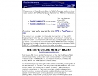 Two live MP3 audio streams provide real-time reception of meteor forward scatter signals, allowing listeners to hear radar echoes from meteoroid disintegration. The system operates on **67.25 MHz**, utilizing an Icom PCR-1000 receiver with a 6-element Yagi antenna pointed skyward. This setup detects reflections from ionized meteor trails created at altitudes of 80 to 130 km, using distant Channel 4 TV transmitters in the southeastern USA as signal sources. Scientists Rob Suggs, Bill Cooke, and Jeff Anderson of the Marshall Space Flight Center Engineering Directorate developed this experimental radar to monitor near-Earth meteoroid activity. A typical day yields about one meteor ping per minute, with significantly higher rates during meteor showers. The optimal listening period is generally around dawn, from 0800 to 1400 UT, due to Earth's orbital motion encountering more space dust on the dawn side. The system's **CW demodulator** processes the 67.250 MHz signal, presenting it at approximately 700 Hz with a 3 kHz bandwidth and AGC off, inverting the passband for Doppler shift analysis.
 -
 End-Fed Half-Wave Antennas (EFHWAs) are analyzed for their utility in portable QRP operations, emphasizing their simplicity, efficiency, and predictable radiation patterns compared to other portable antenna types. The discussion contrasts EFHWAs with vertical antennas, random length wires, and center-fed dipoles, highlighting the common pitfalls of each, such as ground system dependency for verticals and feedline issues for dipoles. The article details the electrical half-wavelength calculation using the formula L (Ft) = 468/F(MHz) and explains how EFHWAs can be resonant on harmonic frequencies, enabling multiband operation. Various deployment configurations are presented, including the inverted L, inverted Vee, sloping wire, and vertical setups, each with specific advantages for radiation angle and polarization. For instance, a vertical EFHWA offers a low angle of radiation suitable for DX contacts without requiring an extensive ground system. The resource also addresses the counterpoise requirements, suggesting a quarter-wavelength wire or connection to a metallic structure for decoupling. A schematic diagram for a simple parallel-tuned circuit tuner, based on the _Rainbow Bridge/Tuner_ design, is provided, detailing component values for 30 and 40 meters, including a 6 microhenry toroidal inductor and a 20-100 picofarad mica compression capacitor. The tuner's adjustment process for SWR matching is also outlined.
 -
 An antenna does not have to be resonant to work, as the primary reason for resonance is to eliminate the need for an impedance-matching device. A non-resonant wire dipole fed with open-wire line and an antenna tuner can function as an effective multiband antenna. Two wires are essential for powering an antenna, ideally with a balanced configuration like a dipole fed by parallel-wire line, though coaxial cable can be used with a 1:1 balun to mitigate RF feedback on the shield. Antenna gain is achieved by shaping and aiming RF energy, concentrating it in a particular direction, as seen in beam antennas or shaped radiation patterns of wire antennas. The function of an antenna tuner is to match the transceiver's 50 Ohm output to the antenna system's impedance, which can vary widely. Wire antennas do not always require center feeding; end-fed long wires or off-center-fed dipoles (Windom antennas) can be used, often requiring a counterpoise or radial system. Dipole antennas do not need to be perfectly horizontal; their legs can be bent, inclined, or even vertical, affecting feed point impedance. Vertical antennas shorter than a half wavelength necessitate a ground system, typically comprising radial wires, with more radials generally leading to greater efficiency. A 1:1 SWR indicates an impedance match but does not guarantee a good antenna, as an inefficient antenna with a poor ground system can still show a perfect SWR while wasting RF as heat. Always using the best feed line affordable is crucial for minimizing loss and maximizing RF signal delivery to and from the antenna.
 -
 Pictures, photos, source code and plans to build a logging frequency counter
 -
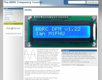 PIC micro controller based frequency counter with LCD readout
 -
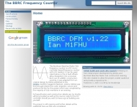 Accurate frequency measurement is crucial for amateur radio operators, particularly when building or troubleshooting transceivers and test equipment. This resource details the construction of a _PIC microcontroller_-based frequency counter, providing a practical solution for precise frequency display. The design incorporates an LCD readout, offering clear visual feedback of measured frequencies. The counter can operate as a standalone unit, useful for general bench testing, or be integrated directly into a receiver. Its built-in offset functionality allows for seamless integration, enabling the display of the received signal frequency rather than the intermediate frequency. The project focuses on accessible components and construction techniques, making it suitable for homebrew enthusiasts. Key features include a measurement range up to **50 MHz** and a compact form factor.
 -
 Ten essential tips and truisms for understanding HF antenna: Non-resonant wire dipole antennas fed with open-wire line and an antenna tuner can function effectively as multiband antennas, as detailed in "The Classic Multiband Dipole Antenna" by WB8IMY in March 2004 QST. Coaxial cable, unlike balanced parallel-wire feed lines, can cause RF to travel on the outer shield braid, leading to RF feedback to the station; a 1:1 balun at the dipole center can mitigate this by isolating the unbalanced coaxial feed line. Antenna gain is achieved by shaping and directing RF energy, with beam antennas concentrating power in a specific direction, and wire antennas also exhibiting shaped radiation patterns. An antenna tuner's primary role is to match the transceiver's 50-ohm output to the antenna system's impedance, allowing modern transceivers to deliver full power. Wire antennas do not always require center feeding; end-fed long wires or off-center-fed dipoles (like the Windom) can be used, though they often necessitate an antenna tuner and a counterpoise or radial network. Dipole antennas do not need to be perfectly horizontal; their legs can be bent or inclined, which affects feed point impedance and may require SWR experimentation with coaxial feed. Vertical antennas shorter than a half wavelength require an efficient ground system, typically comprising elevated or buried radial wires, with more radials generally leading to better efficiency. A 1:1 SWR indicates an impedance match but does not guarantee antenna efficiency; an inefficient vertical antenna with a poor ground system can show a low SWR while wasting most RF as heat. Investing in high-quality, low-loss feed line, especially coaxial cable, is crucial for maximizing RF signal transfer and overall antenna system performance.
 -
 Presents a detailed resource for DXers interested in Non-Directional Radiobeacons (NDBs), MF, HF, and VHF propagation beacons, and various other radiobeacon types. The site offers access to downloadable information files, including an Abbreviations List, NDB List Country List, and NDB Publications List, which serve as foundational materials for newcomers to the hobby of beacon monitoring and DXing. It covers specialized topics such as DGPS beacons, GMDSS DSC mode, and NAVTEX mode, with dedicated sections providing in-depth explanations. A Beacon Photo Gallery showcases diverse radiobeacon types from around the globe, offering visual context for different systems encountered in the field. The platform also facilitates participation in unique monthly Coordinated Listening Events (CLEs), providing guidelines and schedules for these activities. The resource outlines various associated Groups.io lists, including the primary NDB List for radiobeacons (NDBs, Propagation Beacons, VOR systems), the DGPS List for DGPS DXing, Time Signals, LORAN, and WeFAX modes, and specialist groups like NavtexDX and DSC List for GMDSS-DSC. It details how to join these communities for further engagement and information exchange.
 -
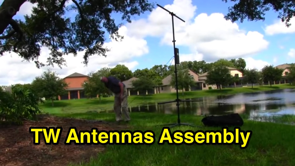 The **TransWorld Antennas TW2010 Traveler HF Portable Vertical Antenna** assembly video provides a visual walkthrough for deploying this popular portable HF antenna. It details the step-by-step process, from unpacking components to final setup, which is crucial for operators preparing for field day operations or DXpeditions. The video focuses on practical aspects, showing how to connect the various elements and secure the antenna for optimal performance. Operators often seek clear assembly instructions for portable antennas like the TW2010 to ensure quick and correct deployment in diverse environments. This visual aid helps clarify potential ambiguities found in written manuals, illustrating the proper handling of the antenna's radial system and telescopic elements. The video serves as a valuable resource for those aiming to achieve efficient operation with the **TW2010 Traveler** in a portable setting. Understanding the assembly sequence can significantly reduce setup time and prevent common errors encountered during initial deployments.
 -
 The Superantennas MP-1 portable HF antenna is analyzed for its design and field performance, particularly its high-Q loading coil and 3/8-inch mounting. The review details the antenna's construction, including an 8-inch vertical section, a large-diameter loading coil tuned by a sleeve, and a 4-foot whip that disassembles into six rods for transport. Initial testing with the supplied 10-foot ribbon cable "ground plane" yielded poor SWR and RF hot conditions, indicating an inadequate ground system. Further experimentation with longer radials and resonant counterpoises for each band improved matching and eliminated RF hot issues, but introduced significant operational complexity. The author notes the difficulty in optimizing both counterpoise length and coil setting without an antenna analyzer, and the sensitivity of the MP-1 to counterpoise deployment. The review also discusses the recommendation to tune for maximum received signals rather than minimum SWR, often necessitating an external ATU due to the antenna's typical low impedance. The **MP-1**'s critical dependence on resonant counterpoises for effective operation, especially when elevated, is highlighted as a major drawback for portable use. The author ultimately sold the antenna, concluding that despite its sound technical design, its fussy nature and the need for extensive counterpoise management or an ATU detract from its portability and convenience compared to simpler, less expensive dipole solutions. The **Superantennas MP-1** is deemed a flawed portable antenna, requiring considerable effort to achieve its claimed performance.
 -
 Antenna directivity and gain are fundamental concepts for any radio operator, as this article from _Electronics Notes_ explains. Real-world antenna designs, unlike theoretical isotropic radiators, do not radiate equally in all directions; their radiation patterns are often visualized using **polar diagrams**. These diagrams illustrate how power is focused in desired directions, crucial for both transmitting and receiving applications. The article clarifies how antenna performance is identical for both transmission and reception, a key principle for understanding antenna specifications. Operators often encounter terms like _beamwidth_, which defines the angle where power falls to half its maximum level, or -3dB. Understanding this parameter is vital for accurately orienting directional antennas like a Yagi. The discussion also differentiates between antenna gain expressed in dBd (decibels over a dipole) and dBi (decibels over an isotropic source), noting that dBi figures will always be **2.1 dB** higher than dBd. This distinction is critical when comparing antenna specifications to ensure an accurate assessment of performance. Furthermore, the article touches on the front-to-back ratio, another important metric for directional antennas, and the balance between maximizing forward gain and achieving an optimal front-to-back ratio.
 -
 Operating a modern amateur radio station, particularly for advanced digital modes or microwave experiments, often requires precise test and measurement equipment. This resource from NI (National Instruments), now part of Emerson, showcases a wide array of hardware and software solutions designed for demanding test objectives. Their portfolio includes modular instruments and configurable software interfaces, such as _LabVIEW_ and _TestStand_, which integrate AI assistance via _NI Nigel™ AI_ for code completion and sequence building. For those involved in RF and microwave work, the offerings extend to vector signal transceivers, RF signal generators, software-defined radios, and spectrum analyzers. These tools are crucial for characterizing antenna performance, optimizing transceiver circuits, or developing custom radio systems. The company emphasizes its 50 years of innovation, with 40 years dedicated to _LabVIEW_, highlighting a long-standing commitment to engineering solutions. The site also details products for data acquisition, electronic test, and wireless design, covering components like CompactDAQ modules for precise sensor measurements and various communication bus interfaces. Their events and perspectives sections offer insights into topics such as 5G technology and strategies for breaking out of testing silos, providing a broader context for their measurement solutions.
 -
 The EA8ALP personal page, hosted on QSL.net, is currently inaccessible, presenting a 404 "Page Cannot Be Found" error. This resource was intended to feature Adelto, an amateur radio operator from the Canary Islands, likely detailing his station, operating activities, or other personal ham radio interests. The QSL.net platform, which hosts over 30,000 amateur radio websites, provides free web and email services to operators and organizations, relying on donations for support. While the specific content of EA8ALP's page is unavailable, the platform's structure suggests it would typically include information relevant to **DXing** and **contesting**, common interests for operators in geographically desirable locations like the Canary Islands. Users encountering this error are advised to contact the website owner directly or use an internet search to locate the intended content, as QSL.net cannot assist with individual site content issues.
 -
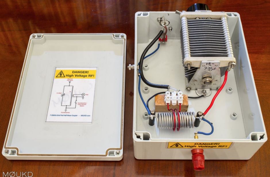 A home made end-fed half-wave antenna coupler with antenna lenght calculator and counterpoise calculator based on center frequency. Includes pictures and drawings along to antenna homebrewing instructions with a home made on air wound transformer
 -
 A homebrew spectrum analyzer, the Specan, provides a crucial measurement capability often missing from the typical amateur radio shack, allowing for detailed analysis of RF signals up to 70 MHz. This double-conversion superheterodyne receiver design incorporates 112 MHz and 12 MHz intermediate frequencies, utilizing an _Si570_ as the local oscillator for fine tuning down to 1 Hz steps. It offers two resolution bandwidths: 300 KHz for broad spectrum sweeps and 1 KHz for precise close-in distortion measurements, achieving an 80 dB spur-free dynamic range at 1 KHz resolution. The project, a reboot of the classic _W7ZOI/K7TAU_ design from November 1998 QST, integrates an _Arduino_ microcontroller for controlling the Si570, managing a front-panel LCD, and communicating with a PC for spectrum plotting. This approach significantly reduces cost compared to commercial units, making advanced RF diagnostics accessible to homebrewers. The Specan can measure carrier suppression, VFO cleanliness, antenna VSWR, transmitter harmonics, and filter passband shapes, providing insights beyond what an oscilloscope or frequency counter can offer. Construction emphasizes modularity and careful shielding, with each stage built and tested individually on unetched copper clad board. The design includes detailed instructions for integrating the Arduino, building the Si570 oscillator, and aligning the various modules, often using the Specan itself for calibration. It requires a well-regulated linear power supply and can be built with common tools and readily available components, making it a practical and rewarding endeavor for those looking to enhance their RF test bench.
 -
 DK4MJ's blog details numerous POTA activations and outdoor amateur radio operations, predominantly from Germany. The content focuses on practical experiences in the field, often involving portable setups and antenna deployments for various bands. Articles frequently describe specific station configurations, power sources, and operational challenges encountered during activations. Many entries include photographs of the operating environment and equipment, such as _portable antennas_ and transceivers, providing visual context to the operational narratives. The blog serves as a personal log of amateur radio adventures, sharing insights into effective portable operating techniques and station optimization for remote locations. Regular updates cover recent activations and related amateur radio topics.
 -
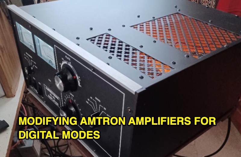 This resource details **cooling modifications** for Ameritron AL82, AL1200, and AL1500 HF amplifiers, specifically addressing heat issues encountered during high-duty-cycle digital mode operation. The author, WD4NGB, observed excessive heat in the tank area and band switch on an AL82, attributing it to insufficient exhaust over the 3-500 tubes and a complete lack of exhaust over the tank area. The modifications aim to prevent common failures such as damaged band switches and deformed insulating materials by increasing airflow and exhaust area. The page describes adding five holes to the chassis for enhanced cooling to the band switch and tank area, alongside enlarging the exhaust area over the inner 3-500 tube and the tank area on the amplifier cover, utilizing expanded metal for safety and RF shielding. The original cover featured 26.25 square inches of exhaust; the modified version significantly increases this to 48.5 square inches over the tubes and introduces an additional 15 square inches over the band switch. These changes are intended to resolve heating problems encountered during heavy, 100% duty cycle use in modes like RTTY or long SSB contests, which typically generate substantial heat. The article also discusses upgrading to a higher output fan, such as the G2E085-AA05-21, and modifying tube sockets for improved airflow and reduced back pressure, citing Tom Rauch (W8JI) of CTR Engineering as a source for parts.