Search results
Query: efhw 40 meter
Links: 7 | Categories: 0
-
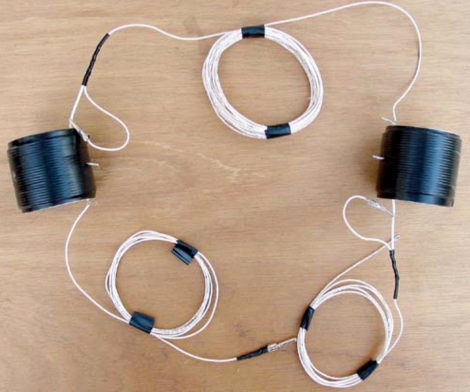 One is an EFHWA for 20-40 meters, and the other is a matching unit for the antenna by n0lx
 -
 This project describes an ARDUINO based automatic antenna tuner, for an end-fed half wave (EFHW) antenna, working on 20 & 40 meter bands
 -
 End-Fed Half-Wave Antennas (EFHWAs) are analyzed for their utility in portable QRP operations, emphasizing their simplicity, efficiency, and predictable radiation patterns compared to other portable antenna types. The discussion contrasts EFHWAs with vertical antennas, random length wires, and center-fed dipoles, highlighting the common pitfalls of each, such as ground system dependency for verticals and feedline issues for dipoles. The article details the electrical half-wavelength calculation using the formula L (Ft) = 468/F(MHz) and explains how EFHWAs can be resonant on harmonic frequencies, enabling multiband operation. Various deployment configurations are presented, including the inverted L, inverted Vee, sloping wire, and vertical setups, each with specific advantages for radiation angle and polarization. For instance, a vertical EFHWA offers a low angle of radiation suitable for DX contacts without requiring an extensive ground system. The resource also addresses the counterpoise requirements, suggesting a quarter-wavelength wire or connection to a metallic structure for decoupling. A schematic diagram for a simple parallel-tuned circuit tuner, based on the _Rainbow Bridge/Tuner_ design, is provided, detailing component values for 30 and 40 meters, including a 6 microhenry toroidal inductor and a 20-100 picofarad mica compression capacitor. The tuner's adjustment process for SWR matching is also outlined.
 -
 The ARRL's End-Fed Half-Wave (EFHW) Antenna Kit is an easy-to-build four-band antenna designed for 10, 15, 20, and 40 meters. Ideal for portable operations, it includes a 49:1 impedance transformer for compatibility with most transceivers. This project, detailed with step-by-step assembly instructions, involves creating a weatherproof enclosure and impedance matching network. The kit simplifies HF operations and supports multiple configurations, making it a versatile tool for amateur radio opertors.
 -
 Building an End-Fed Half-Wave (EFHW) antenna from a kit, as detailed by Frank Bontenbal, PA2DKW, with process photos by Bob Inderbitzen, NQ1R, offers a practical approach for hams. This specific kit, a collaboration between ARRL and HF Kits, targets 10, 15, 20, and 40 meters, making it a versatile option for HF operations. Unlike a center-fed dipole, the EFHW is a half-wavelength antenna fed at one end, which simplifies deployment, particularly for portable use. The construction guide meticulously outlines the assembly of the 49:1 impedance matching network, crucial for transforming the antenna's high impedance (around 2,500 Ohms) to a transceiver-friendly 50 Ohms. Steps include preparing the enclosure by drilling holes for the coaxial connector and antenna connections, followed by the precise winding of enameled copper wire onto a toroid to create the transformer. The guide emphasizes careful insulation removal and soldering for reliable connections. Final assembly involves integrating a 100 pF capacitor for higher band compensation, soldering the transformer's primary and secondary sides, and conducting SWR tests with a 2K7 resistor or a half-wavelength wire. The document also provides examples of wire lengths for different bands, such as 16 feet for 10 meters or 66 feet for 40 meters, demonstrating the transformer's adaptability for various half-wavelength configurations.
 -
 The Portable EFHW antenna for the 40, 20, 15, and 10-meter bands utilizes a broadband transformer with a 1:49 ratio, designed on a PCB by either Jan or DL2MAN. The design incorporates an **FT114 core**, offering an alternative to the FT82 core. The antenna requires precisely 20.5 meters of DX Wire Ultralight for optimal performance. Additional components include DX Wires "Dyneema" 1mm rope and 1mm bricklayers string for structural support. The SWR plot indicates performance at two elevation heights: 5.5 meters (blue line) and 4 meters (yellow line), demonstrating optimization for low-elevation portable use without poles. The antenna's components, including spool and rope tensioners, are available for 3D printing, with spool dimensions scaled to 130% for a length of approximately 110mm. The design emphasizes simplicity and portability, suitable for field deployment.
 -
 This page provides guidance on designing an End-Fed Half-Wave (EFHW) or Random-Length antenna for amateur HF bands, such as 80 or 40 meters. The content explains how to optimize the antenna for multi-band use and match it to a 50-ohm system using an unun. Hams can generate radiation patterns, VSWR charts, and antenna current diagrams for their customized antenna designs. Understanding how antenna dimensions affect performance is essential for successful field operations. The page caters to ham radio operators looking to build efficient and effective HF antennas for their stations.