Search results
Query: end-fed 20m
Links: 15 | Categories: 0
-
 20 meter wire j-pole for 14.2 MHz, a vertical, end-fed half wave antenna by N1LO
 -
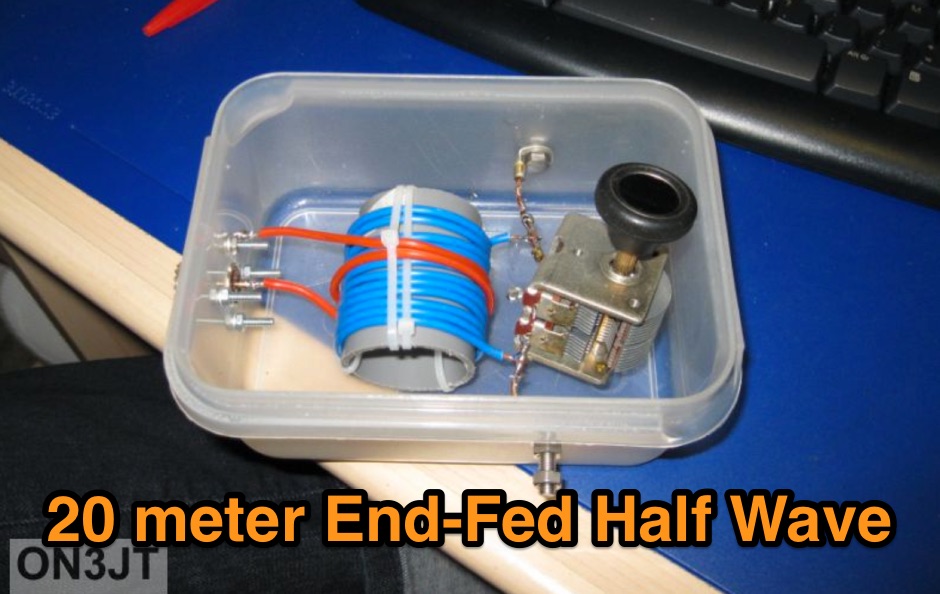
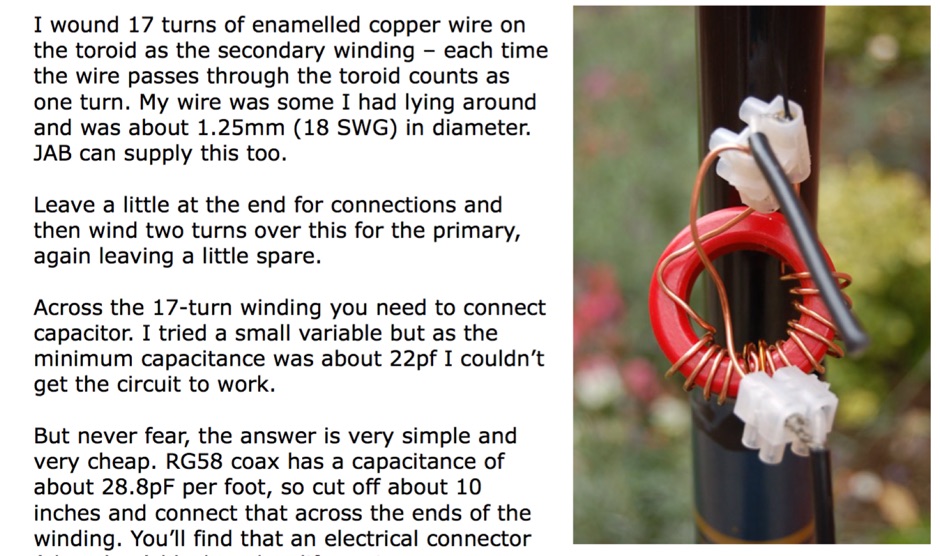
 Constructing an HF End-Fed Half-Wave (EFHW) vertical antenna, the resource details the winding of a monoband matching unit, inspired by _AA5TB_, designed to provide a 50 Ohm impedance match without a ground plane or antenna tuner. It specifies the use of a _T200-2_ ferrite core for the transformer, outlining the 13-turn secondary and 2-turn primary winding process with enamelled copper wire. The document also describes the integration of a coax capacitor, whose length is critical for tuning and varies by band, with specific starting lengths provided for 20m, 17m, 15m, 12m, and 10m operation. The practical application section guides the builder through tuning the antenna using an antenna analyzer, emphasizing the iterative process of spacing secondary windings and trimming the coax capacitor to achieve resonance at the desired band frequency. It highlights the antenna's low angle of radiation, beneficial for DX, and claims up to 2 S-points improvement over a _G5RV_ or similar doublet when used as an omnidirectional vertical. A comprehensive shopping list, including specific part numbers from _Rapid Electronics_, is provided, along with advice on selecting fiberglass fishing poles for support and suitable antenna wire.
 -
-
 A monoband end-fed half wave for 10m, 20m or any other HF band, includes a PDF with detailed information to build your own monoband or multiband antenna
 -
 An end-fed halfwave antenna for 20 meters band with balun pictures and description by PD7MAA
 -
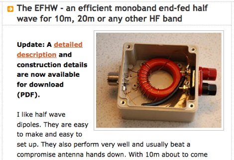 An efficient monoband end-fed half wave for 10m, 20m or any other HF band
 -
 KB6NU end-fed, half-wave antenna article and project
 -
 Constructing an End-Fed Half-Wave (EFHW) antenna offers a practical solution for HF operators seeking a multiband wire antenna without the need for extensive radial systems. This design typically employs a high-impedance transformer at the feed point, matching the antenna's inherent high impedance to a 50-ohm coaxial feedline. The article specifically details a 2012 approach, focusing on a transformer with a 49:1 turns ratio, which is a common configuration for EFHW antennas. The resource outlines the construction of a wire element cut for a half-wavelength on the lowest desired band, with specific coil arrangements enabling operation on harmonically related bands such as 40m, 20m, and 10m. It discusses the physical dimensions and winding details for the matching transformer, often utilizing a ferrite toroid core to achieve the necessary impedance transformation. The content provides insights into the operational principles and practical considerations for deploying such an antenna, including methods for tuning and optimizing performance across multiple amateur radio bands. While acknowledging that the presented information from 2012 may be superseded by newer insights, it serves as a foundational reference for understanding EFHW antenna theory and construction.
 -
 Author experiments end fed half wave antennas using common two conductore speaker wire, this article features a couple of end-fed halfwave wires for the 40M and 20M bands.
 -
 How to Design and Build a Field Expedient End-Fed Half-Wave Antenna for 20m, 40m and 80m. This Shorty 80m EFHW comprises a 49:1 autotransformer (to match the very high impedance at the end of a half-wave wire), a half-wavelength wire for 40m (also a quarter-wavelength for 80m), a loading coil and a short tail wire. The coil and the short tail wire (about 6 feet) make up the other quarter wave on 80m.
 -
 This blog chronicles the development of an 80-meter vertical antenna for amateur radio operation. The author constructs a top-loaded vertical using fiberglass poles, achieving significant performance improvements over their previous end-fed wire antenna. Comparative testing using the Reverse Beacon Network and on-air contacts demonstrates 8-10 dB gain on the east coast. The project evolved to include 40-meter capability through a modified design featuring a four-wire vertical cage, loading coil, and strategic guying system. Despite challenges with signal wobble during windy conditions, the vertical consistently outperforms the end-fed wire, particularly for reaching distant stations during nighttime propagation.
 -
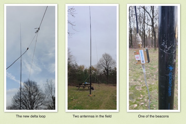 Intrigued by a German OM positive experience with a 20m delta loop, the author replicated the design, noting its favorable 50-ohm impedance compared to their 40m version. Testing against a vertical EFHW, the delta loop excelled within EU but lagged at longer distances. Despite needing more testing, the user leaned towards the EFHW for its overall performance and practicality.
 -
 This page discusses the CLEFHW (Coil Loaded End-Fed Half-Wave) antenna, a portable variation of the popular EFHW design for ham radio operators. The article explains how the CLEFHW allows for backpack portable operation without the need for trees or poles, making it ideal for POTA activations and rapid deployment scenarios. The author details the design, optimization for 20m band, and compares efficiency to full-length wire antennas. Suitable for hams interested in portable antenna solutions and quick setup options for amateur radio activities.
 -
 PH0NO conducted field tests comparing a mobile antenna (DX-UHV) to an end-fed half-wave wire. Results on 20m showed the end-fed wire outperforming the mobile antenna, with a significant difference in signal strength. On 40m, the end-fed wire surpassed the mobile antenna in spots and reach. While the mobile antenna is more practical, the end-fed wire offers superior performance. Further testing is planned.
 -
 This article presents a novel Top Loaded End-Fed Half-Wave (TLEFHW) antenna design for 20-meter ham radio operation. The antenna features a compact 14-foot vertical radiator with a capacitance hat configuration, eliminating the need for radials or ground systems. Using EZNEC modeling and field testing, the design achieves a 1.5:1 SWR across the 20m band with a 4.11 dBi gain. Key features include quick deployment, lightweight construction, and directional radiation pattern with 110-degree beamwidth. The design, while requiring a 45-foot footprint due to the top hat, offers an effective portable solution for amateur radio operators seeking a no-ground, no-tuner 20m antenna option.