Search results
Query: frequency independent
Links: 8 | Categories: 0
-
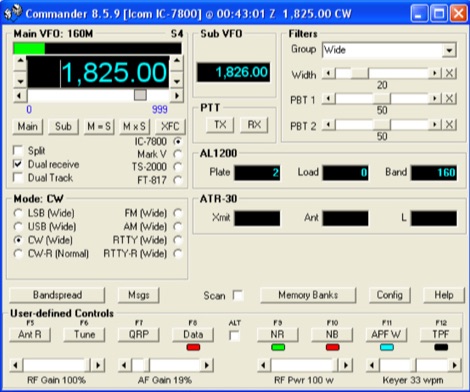 A free application that controls up to 4 Alinco, Elecraft, FlexRadio, Icom, JST, Kachina, Kenwood, TenTec, or Yaesu transceivers, switching between them manually or automatically based on frequency, and displaying frequency-dependent settings for devices like tuners and amplifiers; includes a bandspread, and supports transverters, frequency and mode tracking by an independent transceiver or receiver, SDR-based panadaptors, and SO2R switching with microHam or OTRSP-compliant devices.
 -
 What is NVIS Near Vertical Incident Skywave. This article on NVIS (Near Vertical Incidence Skywave) explores its role in short-range HF communication, covering 0-200 miles. NVIS utilizes antennas with high radiation angles and frequencies below the ionospheric critical frequency to achieve reliable local contact. He details optimal antennas, like low dipoles, and practical tips for maximizing NVIS performance, emphasizing its advantages such as reduced noise and independent operation without repeaters. However, challenges include frequency sensitivity and the need for appropriate antenna setups at both ends for effective communication.
 -
 A fractional bandwidth of up to 30:1 characterizes spiral antennas, making them highly effective across a very wide frequency range, often from 1 GHz to 30 GHz. The resource details two primary types: the **Log-Periodic Spiral Antenna** and the **Archimedean Spiral Antenna**, defining each with specific polar functions and illustrating their planar configurations. It explains that spiral antennas are typically circularly polarized, with a Half-Power Beamwidth (HPBW) of approximately 70-90 degrees, and a peak radiation direction perpendicular to the spiral plane. The content elaborates on critical design parameters affecting radiation, including the total length (outer radius) for lowest frequency, the flare rate ('a' constant) for optimal radiation versus capacitive behavior, the feed structure (often an infinite balun) for high-frequency operation, and the number of turns (typically 1.5 to 3 turns). It also discusses the theoretical impedance of 188 Ohms for Log-Periodic spirals, derived from Babinet's Principle, noting actual impedances are often 100-150 Ohms. The article presents a simple construction method for an Archimedean spiral, demonstrating VSWR and efficiency measurements. Measurements from a constructed spiral antenna show a VSWR that is fairly constant across the band, albeit with a mismatch loss of about 3 dB. The antenna efficiency remains around -5 dB (31.6%) across its operating range, indicating a decent wideband radiator despite opportunities for optimization.
 -
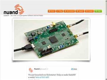 Nuand id the maker of bladeRF - the USB 3.0 Superspeed Software Defined Radio, 300MHz - 3.8GHz RF frequency range Independent RX/TX 12-bit 40MSPS quadrature sampling
 -
 Enables Android users to operate various _miniVNA_ antenna analyzers via Bluetooth, USB, or Wi-Fi, providing a portable solution for RF measurements. The application supports full control over data acquisition, offering features like custom frequency range selection from 1 KHz to the VNA's full range, and automatic screen adaptation for diverse Android device resolutions. It facilitates intuitive, wizard-based calibration for both reflection and transmission modes, saving calibration data for different VNA types (Standard, Pro, Pro with Extender) to avoid repeated procedures. The software displays critical parameters such as SWR, |Z|, Return Loss, Phase, Rs, and |Xs| on 2-axis graphs or Smith charts, with multi-touch gestures for zoom and frequency shift. It includes a frequency generator mode with independent channels and attenuator control for the miniVNA Pro, along with a sweeper function. The cable data mode automatically calculates phase and loss, measures cable length from less than 1 meter to hundreds of meters, and includes a table of common coax cable velocity factors. An experimental X-tal mode measures resonance frequency, Rs, and Q. Data export options include CSV, ZPLOT, and S1P formats, with CSV import capability. The application also features an SM6ENG Audio mode for SWR tuning without visual reference and provides a miniVNA battery voltage indicator. It supports a wide frequency range, with the miniVNA Extender extending coverage up to **1500 MHz**. The application is compatible with Android version 2.2 and later, tested on devices like the _Galaxy TAB 7.7 P6800_.
 -
 Determining the characteristic impedance (Z) of an unknown coaxial cable, a common challenge for many radio amateurs, can be resolved with a straightforward method. The impedance of a coaxial cable is derived from its inductance and capacitance, and importantly, these values are independent of the cable's length or the operating frequency. This means that measuring a random length of cable, such as 20 meters, provides sufficient data for calculation. The core of this technique involves an LC-meter to obtain the inductance (L) in microHenries (uH) and capacitance (C) in microFarads (uF). The impedance is then calculated using the formula Z = L/C. For instance, a measurement yielding L=1.2uH and C=450pF (0.00045 uF) results in an impedance of 51.6 Ohms, closely matching **RG-58** specifications. Similarly, a TV coaxial cable with L=1.8uH and C=320pF (0.00032 uF) calculates to 75 Ohms. While the accuracy of this method, depending on the LC-meter's tolerance, is approximately 10%, it proves sufficiently precise for practical determination of unknown coaxial cable impedance, as noted by Makis, SV1BSX, who credits Cliff, K7RR, for the formula's dissemination.
 -
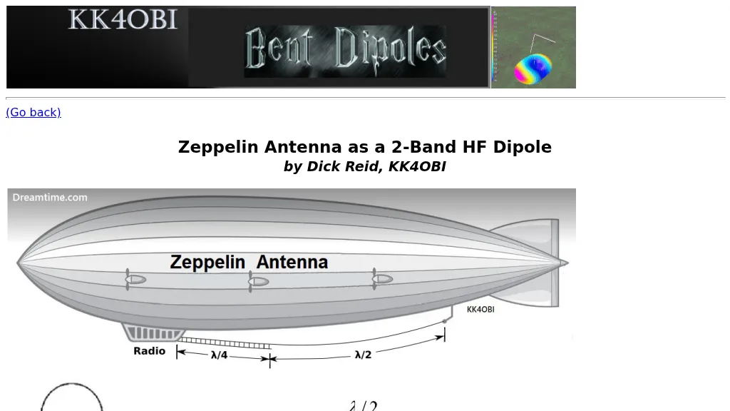 The Zeppelin antenna, a J-type design, is presented as a two-band HF dipole, offering independent operation on harmonically related frequencies. This resource details its electrical configuration, comprising a half-wave radiator end-fed by a quarter-wave matching section, and explores its historical evolution from early Zeppelin airship applications to modern amateur radio use. The article specifically examines how a Zepp antenna tuned to 28.4 MHz (10 meters) exhibits a harmonic relationship with 15.4 MHz (20 meters), noting a frequency ratio of approximately 1.84:1, which deviates from a perfect 2:1 due to factors like elevation, wire separation, velocity factor, and end-effect. Antenna modeling results, including SWR sweeps at 28.4 MHz (1.1 SWR) and 15.4 MHz (1.6 SWR), are provided through Graph 1 and Graph 2, illustrating the antenna's performance across these bands. Current distribution patterns for both the 28.4 MHz (second harmonic) and 15.4 MHz (first harmonic) operations are visually represented in Figure 2 and Figure 3, respectively. The author also includes a 4NEC2 model's "Symbol Conversion file" definitions and calculated #14 wire dimensions for achieving resonance at 28.4 MHz, with the antenna positioned at a height of 33 feet. The discussion further highlights the antenna's versatility, suggesting its potential as a single-band, center-fed, 15.4 MHz half-wave folded end dipole when fed at a specific low current point. This analysis provides practical insights into constructing and optimizing a multi-band Zepp antenna for HF operations, emphasizing its unique harmonic characteristics and physical compactness.
 -
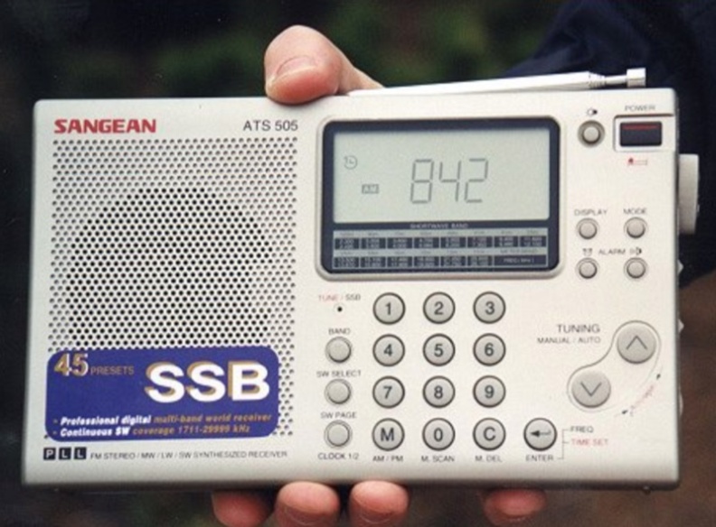 Examines the Sangean ATS-505 portable receiver, a unit introduced in March 2000, providing an in-depth analysis of its capabilities. The review details critical specifications such as its 6 Volt DC power requirement, utilizing 4 AA batteries, and its physical dimensions of 128 x 214 x 39 mm, weighing 840 g without power cells. Frequency coverage spans **LW** from 153-279 kHz, **MW** from 520-1710 kHz, **SW** from 1711-29999 kHz, and FM from 87.5-108 MHz, making it a versatile listener for various broadcast types. Key features highlighted include a backlit display for low-light operation, 45 memory presets for quick access to favorite stations, and the inclusion of Single Sideband (SSB) mode, which is crucial for serious shortwave listening and utility monitoring. The review also draws technical comparisons with other Sangean models, specifically the ATS-404 and ATS-909, pointing out differences in band coverage and operational features. This independent assessment offers practical insights into the ATS-505's performance, helping enthusiasts understand its place within the portable receiver market.