Search results
Query: impedance calculator
Links: 18 | Categories: 1
Categories
-
 Various radio related software, including some antenna analysis, and impedance calculators.
 -
 Unix or linux programme atlc calculates the impedance of electrical transmission lines of totally arbitrary cross section.
 -
 Accurately determining an antenna's feedpoint impedance is crucial for optimal performance, especially when experimenting with new designs or making adjustments. While SWR meters provide basic information, a full complex impedance measurement reveals the resistive and reactive components, which are essential for proper matching. Modern antenna analyzers, like the _Palstar ZM30_ or MFJ259B, simplify this task, but measurements taken through a transmission line require careful interpretation due to impedance transformation. This resource details a calibration method to precisely account for the effects of the feedline. It explains how a transmission line can significantly alter the measured impedance, illustrating this phenomenon with a Smith Chart example where an 80m antenna's [22 + j6] Ohms feedpoint impedance transforms to [82 + j45] Ohms after a 10m line. The guide demonstrates using a transmission line calculator applet, such as the one by W9CF, to reverse this transformation. It outlines the process of calibrating a specific length of RG174 coax, showing how an initial 26ft estimate was refined to **25.85ft** to accurately predict a known 22 Ohm load, significantly improving accuracy over uncalibrated results.
 -
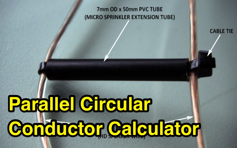 Design a parallel circular wire balanced transmission line with this online calculator. This calculator is a tool for designing balanced transmission lines with a specific desired characteristic impedance Zc and made of parallel circular conductors of a given diameter d.
 -
 1.5 dB of matched line loss can be calculated for a given transmission line using this online tool, which employs a model calibrated from empirical data. The calculator allows radio amateurs to input specific transmission line types, such as _RG-8_ or _RG-58_, and then determine the expected signal attenuation. This is crucial for optimizing antenna system efficiency and understanding power delivery to the radiating element, especially for HF and VHF operations where feedline losses can significantly impact performance. Beyond matched loss, the calculator also provides an estimate for mismatched loss if the Standing Wave Ratio (SWR) is specified. This feature helps operators quantify the additional power loss due to impedance discontinuities between the transceiver, feedline, and antenna, which is a common concern in amateur radio installations. Accurate loss calculations are vital for effective station design and for predicting actual radiated power. The tool's utility extends to various operating scenarios, from fixed station setups to portable deployments, aiding in the selection of appropriate feedline lengths and types to minimize signal degradation. Understanding these losses is a fundamental aspect of maximizing the effectiveness of any amateur radio antenna system.
 -
 Online coax cable impedance calculator
 -
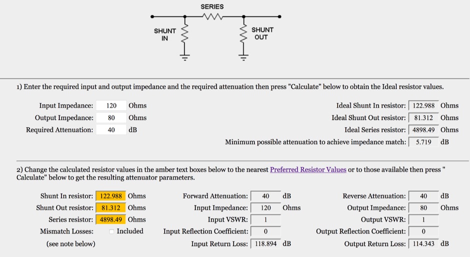 This is an on-line rf attenuator calculator provided free in order to promote the FLEXI-BOX. Calculates the resistor values, attenuation, minimum attenuation, impedance, reflection coefficient, VSWR and return loss of a matching Pi attenuator
 -
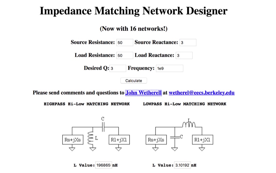 An online multiple calculator of 16 impedance matching networks
 -
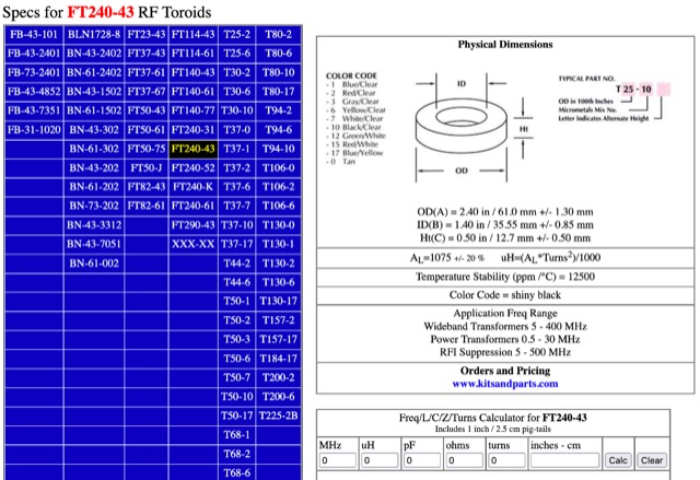 This website provide online calculator for several values about a large variety of toroids. Freq/L/C/Z/Turns Calculator, Impedance Matching Network Calculator
 -
 Microwaves101 provides an extensive repository of information covering fundamental principles of microwave design, targeting engineers and radio amateurs interested in the higher frequency spectrum. The site features a detailed _encyclopedia_ of microwave terms and concepts, alongside practical design considerations for various components and systems. It serves as a foundational reference for understanding RF propagation, transmission lines, and active/passive microwave circuits. The resource includes numerous calculators for impedance matching, filter design, and other critical RF parameters, facilitating hands-on project development. Discussions on **10 GHz** equipment and **24 GHz** projects highlight practical amateur radio applications, extending to operations up to 134 GHz. Content spans from basic theory to advanced topics like MMIC design and antenna characteristics, supporting both educational and practical endeavors in microwave technology.
 -
 Extended Double Zepp measurements for all ham bands, and online calculator. The antenna is constructed much like an ordinary Dipole antenna but with 5/8 Wavelength Elements matched with an added Impedance Matching Section of balanced feed line
 -
 The HB9CV antenna calculator aids amateur radio enthusiasts in designing antennas for VHF and UHF bands. By inputting the working frequency, users can obtain crucial dimensions like dipole lengths and distances. The tool, based on the HFSS antenna model, provides data on impedance, VSWR, and gain, optimizing front/back radiation ratios. It includes tips for fine-tuning using a Г-matching balun and compensating capacitor, ensuring effective performance and minimal VSWR for enhanced radio communications and direction finding.
 -
 Online antenna calculator for a basic 3 elements yagi uda directional antenna. The described antenna design offers a front-to-back ratio of at least 20 dB, a gain exceeding 7.3 dBi, and a bandwidth (SWR < 2) of approximately 7% around the center frequency. It has an input impedance of 50 ohms when using a straight split dipole, which can be substituted with a folded dipole of the same length, increasing the impedance to 200 ohms. A matching balun is required for coaxial feeder connection, and the boom should be made of a dielectric material, like wood.
 -
 The article details the C-Pole antenna project, emphasizing its portability and ease of setup for amateur radio operators. Key features include its compact design as a vertical half-wave dipole that requires no radials, making it functional at various locations. The antenna employs capacitive loading to reduce physical length while maintaining efficiency. It includes practical advice on resonance tuning, impedance matching, and construction materials, along with a calculator for determining dimensions based on desired frequencies. Overall, it presents a user-friendly solution for portable ham radio communication.
 -
 Online impedance calculators grouped by types like Wire inductances, Toroid incuctances, Plane, PAD, Strap inductances, but even Core and Coax Inductances. Air core inductances and mutual inductance groups are also availbale. All these calculators let you input specific paramenters based on the inductor selected and will calculate specific incutance and related dimensions.
 -
 This excel workbook addresses the issue of power loss in transmission lines with complex characteristic impedance ZoZo​. It illustrates the discrepancy between actual loss (0.35 dB) and matched line loss (0.6 dB) using a simplified example, highlighting potential software tool limitations. The RF Feedline Power-Loss Calculator provides accurate end-to-end loss assessments for both microwave and RF applications. This tool is suitable for engineers and students and is compatible with Windows versions of Excel 2016 or later, though it is not compatible with Macintosh systems.
 -
 This page by Arctic Peak provides a detailed explanation on how to use quarter-wave transmission lines as impedance transformers in ham radio antenna work. It explains how to match impedance values by connecting them with a λ/4 transmission line. The page also offers guidance on constructing your own transmission lines with specific impedance requirements, along with a calculator to determine the quarter wave length based on velocity factor and frequency. Useful for hams looking to optimize antenna performance and match transmission line impedance effectively.
 -
 The page features a spreadsheet that calculates power in watt and dBm based on voltage and impedance, power in dBm with a given power and impedance, voltage in millivolts with a given power and impedance, and more. It also converts between millivolt, microvolt, volt, watt, and milliwatt. Useful for hams looking to accurately calculate power and voltage values for radio equipment. Last updated in December 2014.