Search results
Query: led power supply
Links: 16 | Categories: 0
-
 Demonstrates the construction of a **remote antenna tuner** utilizing a standard radio-controlled (RC) servo mechanism to adjust a variable capacitor. The design focuses on enabling remote tuning for narrow-bandwidth antennas, specifically mentioning frame and packing crate antennas, from within the shack. It covers the mechanical arrangement for integrating the servo with a capacitor and provides a circuit diagram for a control unit that generates the necessary 0.5mS to 1.5mS pulse-width modulation (PWM) signals to drive the servo's 180-degree rotation. This setup was successfully tested with up to 20 watts RF power without arcing or adverse effects on the servo, though tuning was performed at 1 watt for VSWR readings. The resource highlights the use of inexpensive, readily available components, such as Futaba servos, and details critical considerations like power supply decoupling with a 47uF capacitor to prevent unintended servo movement upon power-off. The system provides a practical solution for optimizing antenna performance for specific frequencies without manual adjustment at the antenna itself.
 -
 The _Astron RS35m Power Supply Schematic_ provides a detailed circuit diagram for this popular linear power supply, focusing on the rectifier and pass transistor stages. It presents the AC input and DC output sections, illustrating the component layout and interconnections critical for understanding its operation. The schematic is enhanced with specific annotations derived from the December 2005 QST "Hands-On Radio, Experiment #35 Power Supply Analysis." These notes offer insights into the circuit's functionality and potential analysis points, making the diagram more instructive than a bare schematic. The resource serves as a practical reference for hams interested in the internal workings or maintenance of the _Astron RS35m_ unit. This document specifically highlights the key components responsible for voltage regulation and current delivery.
 -
 Two types of home-brewed 12/20 Ampere 13,8volt power supplies, including detailed part lists by ON6MU
 -
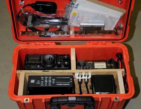 The best way to describe a go-box is a complete amateur radio station in a box. An example is described in this article. The project describes building a portable amateur (ham) radio station, known as a "go-box," housed in a durable orange Pelican case. The go-box contains all necessary radio equipment except for external power and antennae, which are carried separately. It includes items like a Yaesu transceiver, power supply, antenna tuner, speaker, and a clock. The case is designed for mobility and visibility, with a vertical layout to allow in-vehicle operation. Future upgrades might include cooling fans, an LED lamp, and built-in antennae for better functionality in various conditions.
 -
 A 4 AMP / 18V regulated power supply schematic, designed by _ON6MU_, provides a detailed circuit diagram for constructing a robust power source. The design focuses on delivering a stable 18-volt output at up to 4 amperes, crucial for powering various amateur radio equipment. This resource presents a clear visual representation of component interconnections, including rectifiers, filter capacitors, and voltage regulation stages, essential for DIY enthusiasts building their shack infrastructure. The schematic's clarity facilitates understanding the power flow and component roles within the circuit. This circuit design offers a practical solution for hams needing a reliable 18V supply, potentially useful for driving specific transceivers, amplifiers, or accessory circuits. While specific performance measurements or comparisons to other designs are not detailed, the schematic itself serves as a foundational blueprint. Builders can adapt or modify the _power supply_ to suit their particular needs, such as integrating overcurrent protection or fine-tuning the output voltage with adjustable regulators. The straightforward presentation makes it accessible for those with basic electronics knowledge to assemble and troubleshoot.
 -
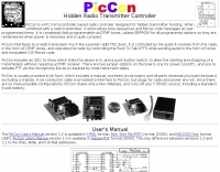 Hidden transmitter hunting, often called fox hunting or Amateur Radio Direction Finding (_ARDF_), presents a unique challenge for radio amateurs. This resource details the _PicCon_ controller, a specialized device designed to automate the transmission of signals for such events. It integrates with a standard radio transceiver, functioning similarly to a packet radio TNC, by controlling the Push-To-Talk (PTT) line and injecting audio tones or modulated CW Morse code into the microphone input. The _PicCon_ unit is field-programmable using DTMF tones received via the radio, storing all settings in EEPROM for power-off retention. Its compact design and low power consumption (a few milliamps from a 7-35VDC source) make it suitable for remote deployment. An onboard LED indicates operational status, and a push-button allows manual start/stop of transmissions without DTMF. Typically supplied as a kit, _PicCon_ includes a PCB, components, and a comprehensive manual (available in HTML, RTF, and PDF formats). The kit provides a six-conductor interface cable, but users must supply radio and power plugs due to varied configurations. Byon, _N6BG_, developed this controller, which is available from the Byonics website.
 -
 Presents a QRP AM/CW transmitter project specifically designed for the 10-meter band, utilizing a crystal oscillator and a collector-modulated AM oscillator. The design employs a 2N2219(A) transistor in a Colpitts configuration, generating 100 to 350 mW of RF output power depending on the 9-18 Volt supply voltage and modulation depth. Frequency stability is maintained by a 28 MHz crystal, with fine-tuning possible via a Ct1 trimmer capacitor for approximately 1 kHz adjustment. The resource details the RF oscillator stage, implemented with a 2N2219 NPN transistor, emphasizing frequency stability and low power dissipation. It also covers the amplitude modulation stage, managed by a 2N2905 PNP transistor, which impresses audio information onto the carrier. Selective components (C3, C4, C7, C5) enhance voice frequencies within a +/- 5 kHz bandwidth, and modulation depth is controlled by R2 and R3. The project includes a 3-element L-type narrow bandpass filter (Ct3, L3, C10) to suppress harmonics and ensure a clean output signal. The project provides a complete schematic diagram, a comprehensive parts list including specific capacitor, resistor, and inductor values, and construction notes for the coils (L1, L2, L3). It also offers practical advice on enclosure requirements, suggesting an all-metal case or a PVC box with graphite paint for RF shielding. Operational parameters such as current draw (27mA@9V to 45mA@16V) and input impedance (50 Ohms) are specified, alongside guidance on antenna matching and the importance of a valid amateur radio license for 10-meter band operation.
 -
 A DIY Automatic Band Decoder (ABD) project, designed for dual-radio operation, addresses the common challenge of integrating band data with older transceivers lacking dedicated outputs. This particular build utilizes an AVR AT90S8515 microcontroller and a 16x2 Liquid Crystal Display (LCD) to provide band information, specifically targeting Kenwood rigs via a computer's LPT port. The design aims for cost-effectiveness while maintaining functionality, offering a solution for hams seeking to add automatic band switching capabilities to their station without significant expense. The project outlines the core components required, including the microcontroller, LCD, and an enclosure, noting that the Printed Circuit Board (PCB) fabrication and AVR programming might present challenges for some builders. It details the input requirements, such as a four-pin input and PTT for each radio, along with a 13.8V DC power supply. The decoder provides 2x6 outputs capable of sinking 500mA, suitable for controlling external devices like antenna switches or filters. Despite the original unit being damaged by a lightning strike in 2004, the author confirms its successful operation prior to the incident and mentions plans for a revised version. The resource includes a schematic in PDF format and images of the finished PCB and assembled unit, demonstrating the practical implementation of the design.
 -
 The m0xpd keyer project utilizes a PIC16F628A microcontroller, offering Iambic A and B modes, adjustable speed from 5 to 40 WPM, and variable weight control. It incorporates a sidetone generator with adjustable frequency and volume, along with a PTT output for transceiver control. The design includes a 16-pin DIL IC socket for the PIC, a 3.5mm stereo jack for the paddle, and a 3.5mm mono jack for the PTT output. Powering the keyer requires a 9V DC supply, which is regulated down to 5V for the PIC. The circuit board layout is designed for through-hole components, facilitating home construction. A detailed schematic and a parts list are provided, guiding builders through the assembly process. The project also discusses the firmware programming for the PIC16F628A, essential for the keyer's functionality. Construction details cover component placement and wiring, ensuring proper operation. The keyer's compact size makes it suitable for portable or shack use, providing a reliable CW interface.
 -
 Operating a ham station often involves encountering radio frequency interference (RFI), RF feedback, or RF burns, which are frequently misattributed to poor equipment grounding. This resource meticulously dissects these assumptions, asserting that RF grounds on the operating desk often merely mask more significant system flaws. It identifies five primary causes for RF problems, including antenna system design flaws, proximity of the antenna to the operating position, DC power supply ground loops, equipment design defects, and poorly installed connectors or defective cables. The content emphasizes that issues like "hot cabinets" or changes in SWR when connecting a ground indicate substantial RF flowing over wiring or cabinets, a phenomenon known as common-mode current. The article provides detailed explanations of common-mode current generation, particularly from single-wire fed antennas like longwires, random wires, and OCF dipoles, which inherently present high levels of RF in the shack. It also illustrates how vertical antennas, lacking a perfect ground system, can excite feed lines with significant common-mode current. Through simulations, the author demonstrates how a dipole without a proper _balun_ can cause RF problems at the operating desk, showing current patterns and voltage distributions on feed line shields. The discussion extends to the proper application of _RF isolators_ and _ferrite beads_, clarifying their role in modifying common-mode impedance on cable shields and cautioning against their use as a band-aid for fundamental system defects. The resource advocates for correcting the actual source of RF problems, such as antenna system issues or poor connector mounting, rather than relying on internal shack grounding or isolators. It highlights that properly functioning two-conductor feed lines, like coaxial or open-wire lines, should result in minimal RF levels at the operating position, even without a desk RF ground. The author shares personal experience, noting that his stations since the late 1970s have operated without RF grounds at the desks, relying instead on proper antenna system design and feed line integrity.
 -
 Maintaining vintage Eddystone receivers often presents unique challenges, as detailed by Victor Jenkins in his refurbishment of an EA12, where his deep understanding of RF circuits ensures optimal performance for daily shortwave listening. Similarly, Gerry O’Hara VE7GUH, a prolific contributor to the EUG website and a trustee, meticulously documented his restoration of an Eddystone S830/2, even addressing an unusual instability issue with a follow-up postscript article and YouTube videos demonstrating the fix. His work, along with numerous other articles on the "Restorations" page, showcases a master's approach to bringing vintage sets back to factory specifications or better. Beyond technical restorations, the EUG also shares compelling historical narratives. One such story recounts the discovery of a long-lost 78rpm recording featuring Eddystone Radio Ltd.'s founder, George Stratton Laughton, and other key figures discussing the company's wartime and post-war contributions to shortwave communications. This six-minute BBC production, transcribed into an MP3 file by Peter Carney, offers a rare auditory glimpse into the company's legacy, highlighting its role in supplying equipment to police, ministries, and expatriate British workers. The community aspect thrives through shared experiences, like Roger Trickett's anecdote about his Eddystone EC10, which has been continuously powered for 50 of its 54 years, traveling across continents and enduring various modifications. Another intriguing account from Roy GM4VKI details the "S640 Identity Crisis," where a seemingly standard S640 receiver turned out to be a masterfully engineered 80/20-meter SSB transceiver built into the original chassis by GI3ZX, showcasing incredible ingenuity from a bygone era of amateur radio.
 -
 his article explores the construction of a PL519 tube amplifier, utilizing Ulrich L. Rohde N1UL's insights. Focusing on a modest 25W continuous output, the design ensures robustness with forced air cooling. The detailed breakdown covers input matching, screen grid voltage generation, bias adjustment, anode power supply, heater power supply, and monitoring circuitry, providing valuable guidance for ham radio enthusiasts.
 -
 The E6AF DXpedition to Niue (OC-040) in 2019 successfully activated a rare DXCC entity, providing thousands of contacts for the global amateur radio community. Operations focused on maximizing QSOs across various **HF bands** and modes, significantly contributing to the DXCC program. The team, led by SP9FIH, meticulously planned antenna deployments and station setups, including a specific focus on **Fox-Hound mode** for digital operations, to ensure robust signal paths and efficient pile-up management. Operational details included specific schedules for CW, SSB, and digital modes, aiming to accommodate different time zones and propagation windows. QSL information and log search functionalities were made available post-operation, facilitating confirmation for thousands of contacts. The expedition encountered logistical challenges, including power supply failure and strict COVID-19 travel restrictions that delayed licensing. Despite these hurdles, the E6AF and E6CI stations provided valuable contacts from Niue, a sought-after location for many DXers.
 -
 A homebrew spectrum analyzer, the Specan, provides a crucial measurement capability often missing from the typical amateur radio shack, allowing for detailed analysis of RF signals up to 70 MHz. This double-conversion superheterodyne receiver design incorporates 112 MHz and 12 MHz intermediate frequencies, utilizing an _Si570_ as the local oscillator for fine tuning down to 1 Hz steps. It offers two resolution bandwidths: 300 KHz for broad spectrum sweeps and 1 KHz for precise close-in distortion measurements, achieving an 80 dB spur-free dynamic range at 1 KHz resolution. The project, a reboot of the classic _W7ZOI/K7TAU_ design from November 1998 QST, integrates an _Arduino_ microcontroller for controlling the Si570, managing a front-panel LCD, and communicating with a PC for spectrum plotting. This approach significantly reduces cost compared to commercial units, making advanced RF diagnostics accessible to homebrewers. The Specan can measure carrier suppression, VFO cleanliness, antenna VSWR, transmitter harmonics, and filter passband shapes, providing insights beyond what an oscilloscope or frequency counter can offer. Construction emphasizes modularity and careful shielding, with each stage built and tested individually on unetched copper clad board. The design includes detailed instructions for integrating the Arduino, building the Si570 oscillator, and aligning the various modules, often using the Specan itself for calibration. It requires a well-regulated linear power supply and can be built with common tools and readily available components, making it a practical and rewarding endeavor for those looking to enhance their RF test bench.
 -
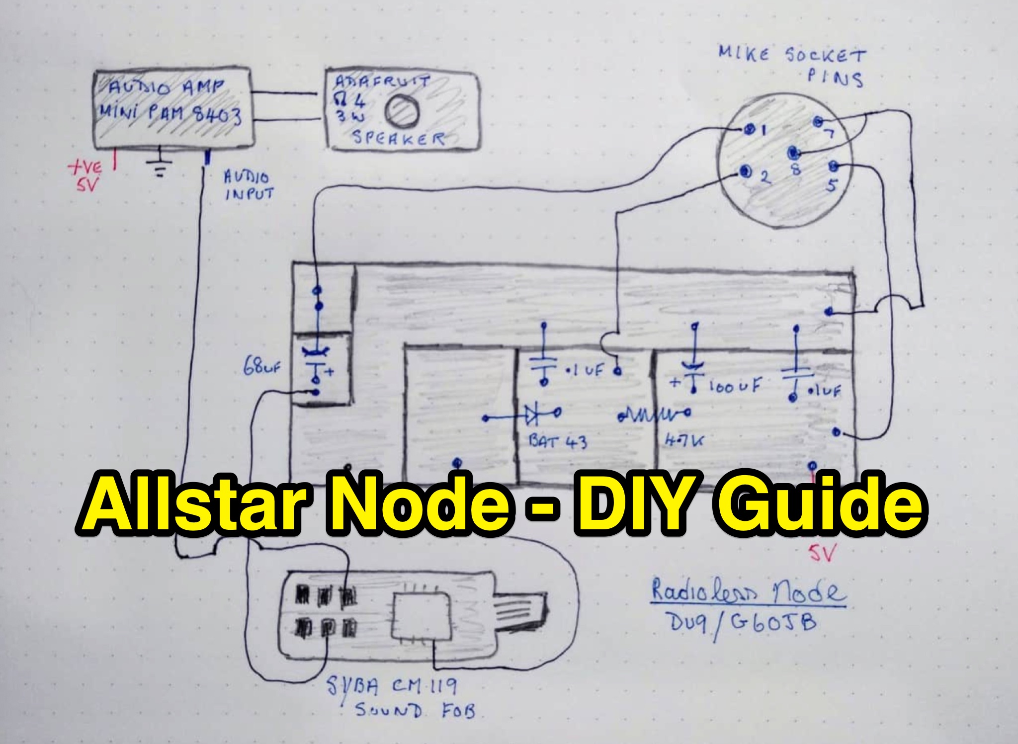 This page provides a detailed guide on how to build your own radioless Allstar node for ham radio operators. It includes information on power supply, components needed, wiring instructions, and tips to avoid common issues like ground loop hums. The author shares personal experiences and recommendations for specific components like microphones, audio amps, and sound fobs. Whether you're a beginner or experienced ham radio operator, this DIY project can help you set up a cost-effective and functional Allstar node for communication purposes.
 -
 Ferrite E-cores offer a practical solution for constructing baluns, especially when connectors are already mounted on cables. These cores, commonly used in mass-produced pulse transformers, allow for multiple turns without dismounting connectors, making them ideal for control and power supply cables. The material of E-cores is generally suitable for common mode baluns up to 15 MHz, providing a cost-effective option for amateur radio operators. E-cores can often be sourced from old switch-mode power supplies, adding to their appeal for those looking to utilize existing resources. A notable example involves a balun on a USB cable using a Ferroxcube E 32x16x9, 3F3 core with four turns, secured by three cable ties. This setup demonstrates the ease of construction and stability achievable with E-cores. Another example features a balun with eight turns of shielded cable with RCA connectors on the same core, achieving 140 uH inductance at low frequencies. The impedance plot for this configuration is measured between the shield ends, illustrating the effectiveness of E-cores in practical applications. The article includes detailed figures and descriptions, providing valuable insights into the construction and application of baluns using ferrite E-cores. These examples serve as a guide for amateur radio enthusiasts looking to enhance their setups with cost-effective and efficient solutions.