Search results
Query: propagation angles
Links: 5 | Categories: 0
-
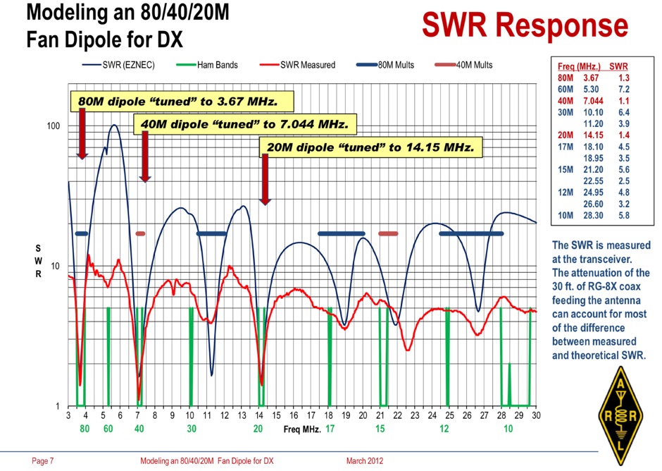 Operating an 80/40/20M fan dipole for DX is analyzed through EZNEC modeling, focusing on the antenna's performance in a real-world, low-height installation. The resource details the physical construction and SWR measurements of the fan dipole, comparing them against EZNEC simulations. It also incorporates High Frequency Terrain Analysis (HFTA) data to illustrate typical DX elevation angles for various regions from New England, providing a crucial context for evaluating antenna patterns. The analysis presents EZNEC-generated azimuth and elevation patterns for each band (80M, 40M, 20M) at specific frequencies, showing gain figures at different elevation angles relevant to DX propagation. It compares the modeled SWR with measured SWR, attributing discrepancies to coax attenuation. The study concludes with observations on the antenna's azimuth performance (omnidirectional within ±1.5 dB) and its less optimal elevation gain at desired DX angles, highlighting the impact of low antenna height on DX capabilities.
-
 This resource is currently a redirect page, indicating the original content is no longer directly accessible at this URL. The page title and description suggest it previously contained a technical comparison of DXpedition antennas, specifically evaluating a 20m Yagi at 25 feet versus vertical antennas on a saltwater beach. The original content likely presented _performance data_ or theoretical analysis for these antenna configurations. Such a comparison would typically involve examining radiation patterns, takeoff angles, and gain figures relevant for long-haul DX from island locations. The resource would have been useful for operators planning DXpeditions to optimize their station setup for maximum signal propagation over saltwater paths, potentially highlighting the **advantages of low-angle radiation** from verticals near conductive ground versus elevated Yagis.
-
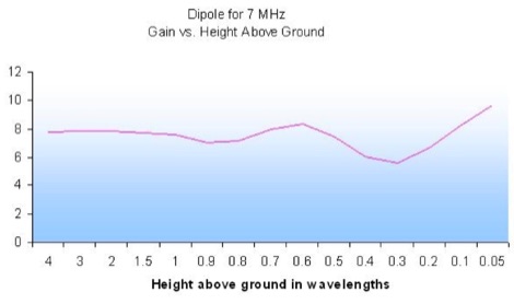 A **dipole antenna's** performance characteristics, specifically its gain and main angle of transmission, are significantly influenced by its height above ground. This resource presents a graphical interpretation of a study conducted by Mike Banz, AA3RL, which explored these critical relationships. The original study's tabular data has been converted into easily digestible graphs, allowing for a clearer understanding of how varying antenna heights affect the **radiation pattern** and overall efficiency. The analysis focuses on the practical implications for amateur radio operators, demonstrating how antenna placement can optimize signal propagation for different communication objectives. Understanding these principles is fundamental for effective station setup, whether aiming for local contacts or long-haul DX. The visual format aids in quickly grasping the complex interplay between physical setup and electromagnetic wave behavior.
-
 This article focus on the radiation angle of vertical antennas and the fundamentals of electromagnetic wave propagation. The calculation of antenna length at 145 MHz is followed by an explanation of electromagnetic wave speed and the link between wavelength, frequency, and velocity. Author discusses the 5/8th wave vertical antenna, namely its performance and the influence of radiation angle on signal transmission. Figures and analogies demonstrate how different antenna types produce distinct radiation patterns. This highlights the importance of selecting the right antenna for a certain purpose, such as local traffic or dxing. The article discusses a variety of factors that affect antenna performance, including SWR, propagation conditions, and equipment dependability
-
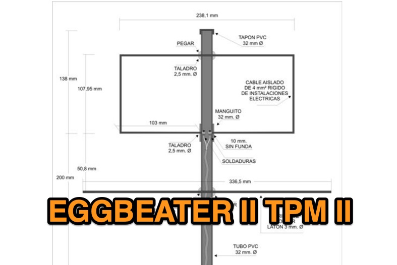 Operating amateur radio satellites presents unique challenges, particularly concerning antenna design and signal propagation. Juan Antonio Fernández Montaña, EA4CYQ, recounts his three-year journey into satellite communication, starting with initial guidance from EB4DKA. His early experiments involved a portable 1/4 wave VHF antenna with four 1/4 wave ground planes, designed for hand-held use to adjust polarity. This setup, paired with an FT-3000M transceiver, allowed full-duplex operation on **VHF** transmit and **UHF** receive, proving effective for early contacts on satellites like AO27, UO14, and SO35. EA4CYQ's experience highlights the critical role of coaxial cable loss and antenna polarization. After encountering significant signal degradation with longer RG213 runs, he experimented with a 1/2 inch commercial cable, noting improved reception but persistent fading due to varying satellite polarities. This led to the construction of an **Eggbeater II** antenna, an omnidirectional UHF design offering horizontal polarization at the horizon and circular right polarization at higher elevation angles. Subsequent modifications resulted in the directional **TPM2** antenna, which provided sufficient gain for LEO satellites with a wide 30-degree lobe, enabling consistent contacts from his home station. The article concludes with practical insights on the performance of the Eggbeater II for both UHF and VHF, and the TPM2 for UHF, emphasizing their utility for portable and fixed operations. EA4CYQ's journey underscores the iterative process of antenna development and the importance of adapting designs to overcome real-world propagation challenges in satellite communications.