Search results
Query: receive antenna hf
Links: 49 | Categories: 0
-
 Low noise, receive only coax loop antennas for 160 - 10 meters HF bands
 -
 Presents the official online presence for Yaesu, a prominent manufacturer of radio communication equipment. The site details their extensive product lines, encompassing amateur radio transceivers, antenna rotators, tuners, amplifiers, and various accessories like microphones, speakers, and power supplies. It functions as a central hub for product information, specifications, and support resources. The resource categorizes its offerings across several key areas, including **Digital Mobile Radio (DMR)** solutions, HF/VHF/UHF transceivers, and specialized receivers and scanners. Each product section typically includes model numbers, feature highlights, and often links to manuals or technical documentation, providing hams with essential data for equipment selection and operation. Beyond amateur radio, the site also covers Yaesu's contributions to aviation and marine radio sectors, illustrating the company's broader scope in wireless communication technology. It serves as a direct portal for accessing manufacturer-provided details, ensuring accuracy and currency for those researching Yaesu gear.
 -
 WiNRADiO Communications, a division of Radixon Group, was established in 1996 to commercialize extensive research in radio communications. The company specializes in integrating radio and computing technologies, offering a diverse product range for government, military, security, and amateur radio enthusiasts. Their product line includes the WR-G65DDCe 'EXCALIBUR Sigma' HF/VHF SDR receiver, noted for its capabilities, and the G31DDC EXCALIBUR, recognized for its price/performance ratio in shortwave listening with improved AMS and Noise Blanker features. The company also produces the G39DDC series EXCELSIOR for serious monitoring, WR-G526e/G527e/G528e modular SDR solutions for high-performance applications like phase-coherent direction finding, and the low-cost WR-G305e/G305i VHF/UHF receivers. Professional counterparts, the WR-G315e/G315i, support APCO P25 decoders and trunking options. WiNRADiO's offerings extend to the PFSL-G3 field strength logging system for mobile signal coverage, advanced multichannel telemetry systems like the MS-8323, and specialized antennas such as the AX-31C Log-Periodic and AX-81S active HF antenna. DRM decoder software is available for G3 Series receivers, enabling clear reception of DRM broadcasts. The WSS-420 Weather Satellite Receiving System and various antenna rotators are also part of their product ecosystem. WiNRADiO supports multiple operating systems, with MacRadio for Apple Macintosh users and LiNRADiO for Linux developers, providing drivers and network receiver solutions like the RLX-810.
 -
 Hong Kong's only full-service amateur radio store. Full line of Amateur Radio and Two-way equipment and accessories from companies such as Yaesu, Icom, Kenwood, Motorola, MFJ, Alinco, Diamond, AOR and many, many more. Knowledgeable staff with many years of experience in the radio business TAX-FREE shopping (no sales, VAT, GAT or other taxes) HF, VHF, UHF transceivers, receivers, walkie-talkies, antennas, antenna tuners, coax and connectors
 -
 manufactures and distributes HF, VHF, UHF and SHF equipment covering 10MHz. - 47.0GHz. Our products include: Wireless LAN / WAN Bidirectional Linear Amplifiers, Low Noise Preamplifiers - LNA's, RF Linear Amplifiers, Relays, Transverter Systems, Frequency Translation Systems, Downconverters, Antennas, Parabolic Dishes, Coaxial Cable, Relays, Antenna Switches, Microwave Test equipment, PC controlled Receivers, Microwave Linear Amplifiers including models for Telemetry, Wireless, and CDMA applications.
 -
 Over 40 years of experience inform the reviews and commentary presented on Dave's Radio Receiver Page, covering a wide array of radio receivers and transceivers. The resource details specific models such as the **ICOM IC-R8600** SDR Communications Receiver, which is lauded as Icom's best wide-band receiver, even surpassing the IC-R9500 in performance. Other notable reviews include the ICOM IC-7300 HF Transceiver, highlighting its direct sampling SDR technology and spectrum scope capabilities, alongside numerous models from Japan Radio Co. (JRC), Kenwood, Yaesu, and various portable shortwave receivers. The content provides practical insights into the performance and characteristics of each radio, often drawing comparisons between models. For instance, the early issues with the AOR AR7030 receiver's Bourns mechanical encoders are thoroughly documented, including AOR's eventual switch to higher-quality Alps encoders. The page also features reviews of antennas like the MFJ-1026 Noise Canceling Signal Enhancer and various power supplies, offering a holistic view of radio monitoring setups. The author's "2 ear / 2 eye method" emphasizes real-world listening experiences over laboratory measurements, providing a unique perspective on equipment utility.
 -
 Constructing a Lindenblad antenna for 137MHz NOAA satellite reception involves specific design considerations for optimal performance. The resource details the use of 4mm galvanised steel fencing wire, 300-ohm television ribbon cable, and wood/plastic components for the antenna structure. Key dimensions for a 137.58MHz-resonant antenna are provided, derived from the ARRL Satellite Handbook, specifying s, l, w, and d as 42, 926, 893, and 654mm respectively. The antenna is designed for Right Hand Circularly Polarised (RHCP) signals, requiring the four folded dipole elements to be tilted clockwise by 30 degrees. A significant aspect covered is impedance matching between the antenna's 75-ohm impedance and a typical 50-ohm receiver input. A twelfth-wave matching transformer, constructed from 117mm sections of 50-ohm RG-58 and 75-ohm RG-59 coax with a 0.66 velocity factor, is described. The article also addresses coaxial cable and connector selection, recommending 75-ohm Type-N connectors for RG-6 cable in professional setups and F56/F59 connectors for general use, while strongly advising against PL-259/SO-259 connectors for VHF. Strategies for mitigating Radio Frequency Interference (RFI) are discussed, including antenna placement to shield from local TV transmitters and the use of commercial or DIY band-pass filters, such as cavity resonators or helical notch filters, along with ferrite chokes on coaxial cables. Antenna orientation is explored, noting the Lindenblad's 'cone of silence' directly overhead and its maximized sensitivity towards the horizon. An experimental vertical tilt of 90 degrees is presented as a method to improve overhead reception and reduce interference from strong horizontal signals, particularly relevant in high RFI environments like the Siding Spring Observatory site.
 -
 The Q-signal **QRP** signifies a request to reduce power, and in amateur radio, it defines operating with 5 watts or less for CW and 10 watts or less for SSB. This article addresses common inquiries from new hams regarding the practice, its benefits, and implementation methods. It explains how a 5-watt QRP signal, compared to a 100-watt signal, typically results in only a 13dB drop in signal strength, equating to about two S-units, still providing solid copy under most conditions. Hams choose QRP for various reasons, including seeking a greater challenge in DXing or contesting, reducing band interference, or enabling portable field operations with lightweight, battery-efficient equipment. A modern single-band CW transceiver, key, and antenna can fit into a pocket, offering receiver performance comparable to commercial rigs and extended operation on a small battery. This portability facilitates operations in remote locations where higher-power setups are impractical. Operating QRP can involve simply reducing power on an existing commercial HF rig or building a dedicated QRP transceiver from a kit, such as the **Wilderness Radio SST** with its 2-watt output and 15mA receive current draw. While SSB is viable, CW remains the most popular and efficient mode for QRP due to its superior signal-to-noise ratio. The article lists common QRP calling frequencies across 160m through 10m bands for both CW and SSB, and highlights organizations like QRP ARCI and NorCal that support the QRP community.
 -
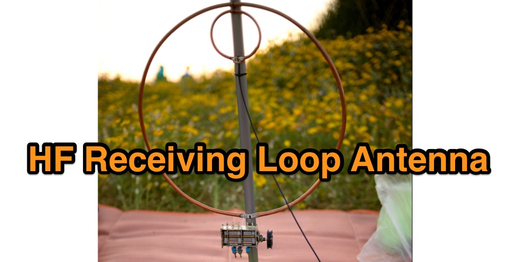
 Demonstrates the construction and measurement of a single-turn HF receiving loop antenna, built from common materials like electrical conduit and lamp cord. The resource details the physical dimensions, including a 4-meter circumference, and calculates the theoretical inductance at approximately _6.4 uH_. It outlines a method for determining resonant frequencies across the 4-17 MHz range using a _C Jig_ and a _VR-500 receiver_, coupling the loop with a ferrite ring. The article also discusses the impact of receiver coupling on the loop's Q factor, noting a degradation in sharpness due to the transformer's reflected impedance. Analyzes the observed resonant frequency patterns, highlighting an unexpected rise in the loop's effective inductance at higher frequencies, particularly above 13 MHz. While some increase is attributed to distributed capacitance, the rate of rise suggests further investigation. The experimental setup provides practical insights into the challenges of maintaining high Q in simple receiving loops and offers a comparative reference for other homebrew antenna projects, such as those by _VK2TPM_.
 -
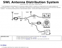 a methodology for connecting multiple LF/MF/HF receivers to a single antenna via readily available and inexpensive 75-ohm TV cable.
 -
 Optimizing a G5RV or ZS6BKW multiband wire antenna for HF operation often involves addressing common SWR issues and understanding feedline characteristics. This resource chronicles the construction and performance evaluation of a G5RV, initially built for 80m, 40m, 15m, and 10m bands, by a newly licensed Foundation operator. The author details the selection of materials, including 3.5 mm stainless steel wire for the doublet arms and enameled copper wire for the open-wire feeder, and the initial decision to omit a balun based on common online information. The narrative highlights the initial disappointing performance, characterized by high receive noise and poor signal reports on 80 meters, despite the transceiver's internal ATU achieving a 1:1 match. This led to experimentation with a coax current balun and further research into G5RV myths, such as SWR claims and the necessity of a balun. The author then describes modifying the antenna to the ZS6BKW configuration, which involves specific changes to the doublet and feedline lengths, and integrating a 1:1 current balun wound on a ferrite toroid. The modifications resulted in improved reception and transmit performance across the bands.
 -
 For amateur radio operators engaged in **radio direction finding** (RDF) and **transmitter hunting** (T-hunting) activities, this resource provides a catalog of printed circuit boards (PCBs) for constructing various DF and foxhunt-related projects. The offerings include PCBs for 80-meter fox transmitters and receivers, UHF fox transmitters with audio recording capabilities, and several designs for general-purpose radio direction finders. Specific projects like the "Simple 80M ATX-80 Transmitter" and the "N0GSG DSP Radio Direction Finder" are listed, along with attenuator boxes and specialized components for Doppler DF systems. The catalog details PCBs for projects published in prominent amateur radio magazines such as *73's*, *CQ*, *QST*, and *PE*, indicating their origin and design pedigree. For instance, the "Montreal Fox Controller" is sourced from the *Homing-In* column by Joe Moell, K0OV. The resource also lists components for advanced Doppler DF systems, including main boards, LED display boards, and antenna switch boards, with options for programmed PIC microcontrollers. Pricing for each PCB is provided, allowing hams to acquire the necessary components for their DIY RDF endeavors.
 -
 Operating on the 2200m band (135.7-137.8 kHz) often presents challenges for amateur radio transceivers, which typically exhibit poor receiver performance at these very low frequencies. This project addresses the issue by providing a design for a dedicated 137 kHz antenna preamplifier, specifically tailored to improve signal reception for radios such as the _Yaesu FT-817_. The preamplifier circuit utilizes a low-noise FET input stage, crucial for minimizing self-generated noise and maximizing the signal-to-noise ratio from weak LF signals. The design includes a detailed schematic, component values, and construction notes, enabling homebrewers to build a functional unit. The goal is to achieve significant gain, making the faint signals on 2200m more discernible and improving overall band usability. Key design considerations include impedance matching to typical antenna systems and ensuring stable operation across the narrow LF segment. The circuit aims for a **low noise figure** and sufficient amplification to overcome the inherent limitations of general-purpose HF transceivers when operating below **200 kHz**.
 -
 Sherwood Engineering Inc. (SEI) offers a repository of technical presentations and white papers focused on optimizing amateur radio transceiver and receiver performance. Content includes detailed analyses of _roofing filters_, transmitted IMD, and receiver characteristics, with specific discussions on products like the Drake R-4C and Icom IC-781. Presentations from events such as Dayton Contest University (2008-2014) cover topics like "How To Optimize Rig Performance," "Transceiver Performance: 10 Years of Change," and "Choosing a Transceiver: Far from Simple." Additional white papers address HF mobile antenna efficiency, ground screen alternatives to buried radial systems, and common receiver problems with solutions. The site also provides historical product information for items like the SE-3 MK IV synchronous AM detector and various 455 kHz mechanical and crystal filters, though many products are no longer in production. Receiver test data and alignment tips for the R-4C are also available, offering insights into rig modifications and performance enhancements.
 -
 The Yaesu FT-1000MP Mark-V, introduced at Dayton 2000 Hamvention, features a higher RF power of **200 W PEP** and a Class-A amplification SSB mode at 75 W. Key enhancements include an _Interlocked Digital/Analog Bandwidth Tracking system (IDBT)_, a Variable Front-End Filter (VRF) preselector, and improved ergonomics, notably a multi-function shuttle jog dial. This model, a successor to the 1996 FT-1000 and FT-1000MP, was designed to compete with high-end transceivers, despite its retail price of $4200 initially. The transceiver's physical dimensions are 406 x 135 x 348 mm (16 x 5.3 x 13.7 inches) with a weight of 14 kg (31 lbs), making it substantial. Its rear panel offers over 20 connections, including power, external DSP speaker, BAND DATA I/O, ALC, and multiple interface jacks for DVS-2, Packet, and RTTY. The unit also provides two keyer inputs, a DB9M serial interface for CAT, and two PL female antenna connectors, plus additional receive antenna jacks. Despite its advanced internal architecture, including two independent receivers with their own IF filters and AGC loops, the display technology, utilizing fluorescent discharge rather than LCD, contributes to an older aesthetic. The control panel is extensive, featuring 92 knobs and buttons, alongside numerous LED indicators for various modes and functions.
 -
 The antenna was built to be used for shortwave listening with a Tecsun PL-660 radio receiver. Later it was used with Yaesu VX-6 handheld transceiver and with Yaesu FT-817ND for shortwave listening.
 -
 Demonstrates the operational status and reception reports for the SK6RUD/SA6RR QRPP beacons, which transmit on 478.9 kHz, 1995 kHz, 10.131 MHz, and 40.673 MHz. These beacons utilize extremely low power, with the 630-meter beacon operating at approximately 0.1 watt ERP into an L-antenna, showcasing the potential for long-distance contacts under favorable propagation conditions. The site details the specific frequencies and antenna types employed, such as a vertical at 500 kHz and a 1/4 vertical for higher bands. The resource compiles over 10,530 reception reports from amateur radio operators worldwide, logging details such as date, time, band, RST signal report, locator, distance, and receiver setup. Notable long-distance reports include a 500 kHz reception by AA1A-Dave from 5832 km in 2008 and a 10.133 MHz reception by ZL2FT-Jason from 17680 km in 2010, illustrating the global reach of these low-power transmissions. Each log entry provides specific equipment used by the reporting station, including transceivers like the Yaesu FT817, ICOM IC-7300, and various antenna configurations such as coaxial mag loops, inverted Ls, and end-fed wires. The primary objective of the SK6RUD beacons is to challenge conventional notions of power requirements for effective two-way communication, proving that contacts over significant distances are achievable with minimal output. The site also includes a submission form for new reception reports, fostering community engagement and continuous data collection on propagation phenomena across different bands. The detailed logs offer practical insights into real-world propagation characteristics and the efficacy of QRPP operations.
 -
 Receive-only loop antennas have some nice response characteristics that make them ideal when used for reception of skywave signals.
 -
 A 200 kHz bandwidth digital transmission system for image transfer in the Amateur Service is under development, specifically targeting VHF allocations. John B. Stephensen, KD6OZH, leads this project under an FCC Special Temporary Authority (STA) valid until September 10, 2006, authorizing emissions up to 200 kHz bandwidth in the 50.3-50.8 MHz segment. Current regulations typically limit bandwidths to 20 kHz on VHF amateur bands, making this STA crucial for testing wideband digital modes. The modem, a modified **OFDM** (Orthogonal Frequency Division Multiplexed) unit, was initially tested on the 70-cm band. It splits a high-rate data stream into multiple low-rate subcarriers to mitigate multipath echoes. The system uses a DCP-1 card with a Xilinx XC3S400 FPGA and Oki Semiconductor ML67Q5003 microcontroller. The transmitter, located at 36d 46m 30s N, 119d 46m 22s W, generates 150 WPEP into an 8 dBi gain vertical antenna, while the mobile receiver uses a Ham-stick. Three data formats for 50, 100, and 200 kHz channels are being tested, with encoded data rates of 96, 192, and 384 kbps. Verilog code for the VHF OFDM modem is 95% simulated, with modifications from the UHF version including increased filter coefficient precision and a change from Ungerboeck **TCM** to BICM for improved performance over fading paths. Final tests will involve one-way over-the-air measurements of bit error rates and coverage area.
 -
 US amateur radio antenna manufacturer, design and build monoband, dual band and multiband Yagi Antennas for HF bands as well as receive antenna systems
 -
 Optimizing weak signal reception on the HF bands, particularly in the presence of strong local QRM, often necessitates specialized receiving antenna systems. This resource details the _HI-Z Antennas_ product line, focusing on phased vertical arrays designed for superior noise rejection and directivity. It covers components such as the 4-Square and 8-Element array controllers, which allow for rapid switching of receive patterns, and dedicated low-noise preamplifiers to improve system sensitivity. The site also presents various bandpass filters, crucial for mitigating out-of-band interference and enhancing the dynamic range of the receiver. The HI-Z systems are engineered to provide significant front-to-back and side rejection, often yielding **20-30 dB** of attenuation to unwanted signals, which is critical for DXing and contesting. Users can achieve a notable reduction in local noise, allowing for the discernment of signals that would otherwise be buried. The array controllers facilitate quick pattern changes, enabling operators to null out interference or peak weak signals from distant stations, effectively extending the reach of their receive capabilities by improving the signal-to-noise ratio.
 -
 The Buddipole Deluxe, a portable HF/VHF antenna system, receives a practical assessment from IW5EDI after a month of field use. The author, constrained by antenna restrictions, highlights the system's crucial role in enabling portable operations, even managing sporadic digital activity from a balcony. Direct comparisons to a fixed 3-band dipole reveal surprisingly comparable signal reports on 15, 17, and 20 meters, underscoring the Buddipole's effectiveness in real-world scenarios. Tuning the Buddipole proves straightforward on bands down to 20 meters, though the review notes significant challenges with SWR on lower bands like 40 meters, where achieving better than 3:1 SWR was problematic. Observations also include SWR variations with dipole rotation and mast height, suggesting environmental factors play a role. The overall manufacturing quality of the antenna and its accessories, including the tripod and carry bag, is deemed good, despite a minor issue with a pole connector. Looking ahead, the author plans to construct a homemade Buddipole version, possibly optimized for the 30-meter band, specifically for PSK31 operations from an apartment. This personal project reflects a common amateur radio practice of adapting commercial designs for specific needs, further extending the utility of portable antenna concepts.
 -
 The _Sci.Electronics FAQ: Repair: RFI/EMI Info_ document, authored by Daniel 9V1ZV, provides a detailed analysis of computer-generated RFI/EMI, focusing on its impact on radio reception. It identifies common RFI sources such as CPU clock rates (e.g., 4.77 MHz to 80 MHz), video card oscillators (e.g., 14.316 MHz), and even keyboard microprocessors, all of which generate square-wave harmonics across HF and L-VHF regions. The resource outlines a systematic procedure for pinpointing RFI origins, including disconnecting peripherals and using a portable AM/SW receiver with a ferrite rod antenna to localize strong interference sources. The document categorizes RFI mitigation into shielding, filtering, and design problems, offering practical solutions for each. It recommends applying conductive sprays like _EMI-LAC_ or _EMV-LACK_ to plastic casings of radios, monitors, and CPUs to create effective Faraday cages, emphasizing proper grounding and avoiding short circuits. For filtering, the guide suggests using line filters, ferrite beads, and toroids on power and data lines, and small value capacitors (e.g., 0.01 uF for serial/parallel, 100 pF for video) to shunt RFI to ground. It also discusses the use of bandpass, high-pass, low-pass, and notch filters on the receiver front-end or antenna feed to combat specific in-band noise.
 -
 The Superantennas MP-1 portable HF antenna is analyzed for its design and field performance, particularly its high-Q loading coil and 3/8-inch mounting. The review details the antenna's construction, including an 8-inch vertical section, a large-diameter loading coil tuned by a sleeve, and a 4-foot whip that disassembles into six rods for transport. Initial testing with the supplied 10-foot ribbon cable "ground plane" yielded poor SWR and RF hot conditions, indicating an inadequate ground system. Further experimentation with longer radials and resonant counterpoises for each band improved matching and eliminated RF hot issues, but introduced significant operational complexity. The author notes the difficulty in optimizing both counterpoise length and coil setting without an antenna analyzer, and the sensitivity of the MP-1 to counterpoise deployment. The review also discusses the recommendation to tune for maximum received signals rather than minimum SWR, often necessitating an external ATU due to the antenna's typical low impedance. The **MP-1**'s critical dependence on resonant counterpoises for effective operation, especially when elevated, is highlighted as a major drawback for portable use. The author ultimately sold the antenna, concluding that despite its sound technical design, its fussy nature and the need for extensive counterpoise management or an ATU detract from its portability and convenience compared to simpler, less expensive dipole solutions. The **Superantennas MP-1** is deemed a flawed portable antenna, requiring considerable effort to achieve its claimed performance.
 -
 Commsaudit uk, i/q quadrature , hf receivers, rf, multicoupler, multicouplers, switch matrix, antenna matrices, masthead amplifier,, vhf receiver, uhf,
 -
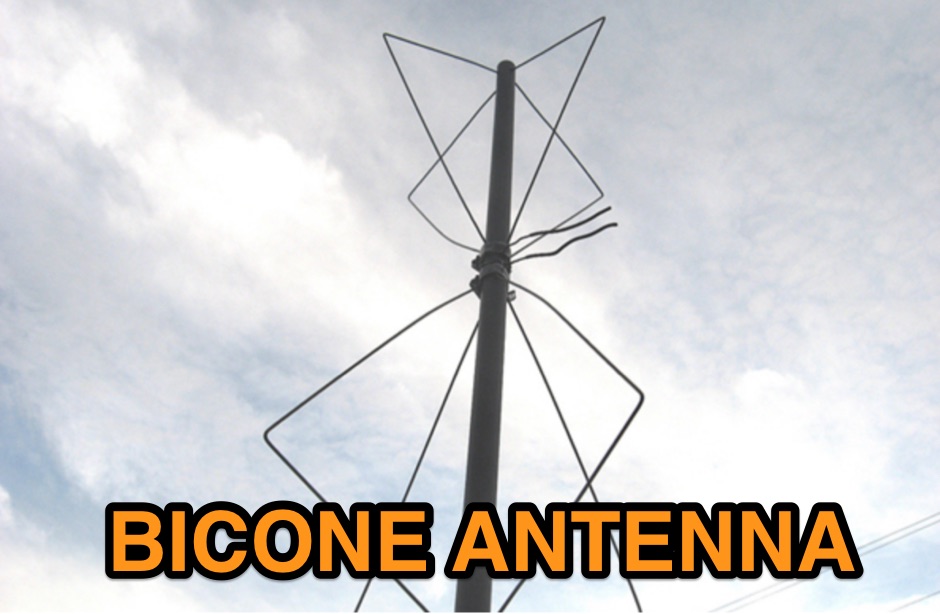 Homebrewing a vhf bicone antenna with 8 clothes hangers and 4 feet of Sch40 non-metallic rigid conduit
 -
 SPX Communication Technologies, operating under the TCI International brand, presents a range of radio frequency (RF) solutions primarily for government, defense, and commercial sectors. The offerings include advanced systems for spectrum monitoring, communications intelligence (COMINT), and high-frequency (HF) and medium-frequency (MF) broadcasting and communication antenna systems. Specific product lines encompass _Blackbird_ COMINT systems, _Scout_ spectrum monitoring receivers, and various antenna arrays designed for robust performance in challenging RF environments. The resource details the capabilities of these systems, such as wideband signal detection, direction finding (DF), and signal analysis, crucial for intelligence gathering and regulatory compliance. It also highlights the engineering behind their antenna designs, which are optimized for specific frequency ranges and operational requirements, including high-power broadcast applications and secure military communications. The information presented emphasizes the integration of hardware and software for comprehensive RF situational awareness. The company's focus on empowering partners to "Command the Spectrum" underscores its commitment to delivering critical tools for signal interception, analysis, and management across diverse operational landscapes.
 -
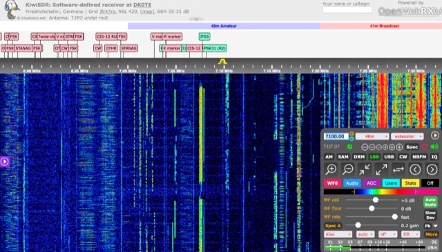 Online internet HF LW MF web receiver based in Baden-Wuerttemberg cooperative state university Ravensburg Campus Friedrichshafen running a T2FD antennan under roof.
 -
 The Kenwood TS-870S HF transceiver features two state-of-the-art 24-bit 20 MIPS DSP chips, providing over 100dB out-of-passband attenuation and CW bandwidth adjustable to 50 Hz. It operates across 160-10 meters with 100 watts output, incorporating digital filtering, a beat canceller, and 100 memory channels. The radio also includes a transmit equalizer, RX antenna input, and a K1 Logic Keyer, enhancing signal processing and operational flexibility for amateur radio operators. Advanced capabilities include IF stage DSP, dual noise reduction, and an auto notch filter, all contributing to superior signal reception and clarity. The TS-870S offers a variable AGC, voice equalizer, and an RS-232C port for computer control, with Windows™ software supplied. Its built-in automatic antenna tuner functions on all bands for both transmit and receive modes, streamlining station setup and operation. Available accessories such as the DRU-3A digital recording unit, SO-2 high stability crystal oscillator, and VS-2 voice synthesizer option further extend the transceiver's utility. The unit requires 13.8 VDC at 20.5 Amps and is supplied with an MC-43S hand microphone, making it a comprehensive station component.
 -
 Sixty-meter repeaters typically use a 1 MHz frequency separation between input and output, while 2-meter repeaters commonly employ a **600 kHz** split and 70-centimeter repeaters use a **5 MHz** offset. This article details the fundamental technical principles of amateur voice repeaters, explaining how they extend VHF/UHF communication range by receiving on one frequency and simultaneously retransmitting on another. It covers essential components such as receivers, transmitters, filters, and antennas, often situated on elevated locations for optimal coverage. The resource delves into the critical challenge of _desensing_—where the repeater's strong transmit signal overpowers its own receiver—and the engineering solutions employed, including antenna separation and the use of high-Q cavity filters. It also explores various control and timing systems, from basic squelch activation to more sophisticated microcontroller-based boards that manage functions like voice identification, time-out timers, and fault protection. Different access methods are discussed, including open access, toneburst, CTCSS subtone, and DTMF, each offering distinct advantages for managing repeater usage and mitigating interference. Furthermore, the article examines repeater linking, both conventional RF methods and modern internet-based solutions, highlighting how linking expands coverage and promotes activity across multiple repeaters or bands. It introduces less common repeater types such as 'parrot' repeaters, which use a single frequency and digital voice recording, and linear translators, capable of relaying multiple signals and modes simultaneously across different bands, often found in amateur satellites.
 -
 Designing and constructing a two-element receiving loop antenna array for HF operation involves specific considerations for achieving high directivity and noise reduction. This resource details a homebrew system comprising two 30-inch diamond-shaped loops, spaced 20 feet apart, which are fed through mast-mounted preamplifiers and passive signal combiners. The operational principle relies on adjusting phase delays between elements via precise _Belden 8241_ coaxial cable lengths, optimized for specific bands from 160m to 20m. Performance data, derived from _EZ-NEC_ modeling, illustrates consistent 90° azimuth-plane beamwidth and low take-off angles across the target bands, with _Receiving Directivity Factor_ (RDF) values comparable to a 300-foot Beverage antenna. The article presents detailed elevation and azimuth plots for 20m, 30m, 40m, 80m, and 160m, demonstrating the array's ability to provide strong response at low DX angles while also supporting _NVIS_ signals. Key components like the _DX Engineering RPA-1_ preamplifier and _DXE RSC-2_ signal combiner are discussed, alongside the importance of impedance matching to preserve antenna patterns. The construction emphasizes self-contained elements that do not require ground radials, offering a compact solution suitable for suburban environments and stealth installations, with a focus on optimizing receive performance independently from transmit antennas.
 -
 High Speed Multimedia (HSMM) radio, as introduced by John Champa, K8OCL, represents a significant advancement in amateur radio's digital capabilities, moving beyond traditional keyboard modes like packet radio. This initiative, driven by ARRL's Technology Task Force, focuses on developing high-speed digital radio networks capable of up to 20 megabits per second. HSMM primarily facilitates digital voice (DV) and digital video (ADV), enabling real-time video transmission from emergency scenes to an EOC without expensive ATV gear, often requiring only a laptop, a PCMCIA card, a digital camera, and a small antenna. The working group's initial efforts concentrate on cultivating microwave skills within the amateur community to build and support portable and fixed high-speed radio-based local networking, or **RLANs**. These networks prove invaluable for RACES and ARES organizations, as well as homeland security and other emergency communications. Field Day exercises and simulated emergency tests (SETs) are encouraged to hone skills in rapid site surveys and deploying broadband HSMM microwave radio networks, with examples like linking Field Day logging stations or antenna test results at the Midwest VHF-UHF Society Picnic 2003. Getting started with HSMM often involves adapting off-the-shelf **IEEE 802.11** (WiFi) equipment to comply with amateur radio regulations, typically operating in the 2.4 GHz ISM bands. While consumer WiFi gear has range limitations under Part 15 rules, proper setup under amateur regulations can extend coverage significantly, with test networks like the Hinternet achieving 5-15 mile ranges at 54 M bit/s using small mast-mounted dish antennas. Careful selection of equipment with external antenna ports, high transmit power, and low receive sensitivity is crucial, along with using low-loss coaxial cable like LMR-400 for optimal performance at these frequencies.
 -
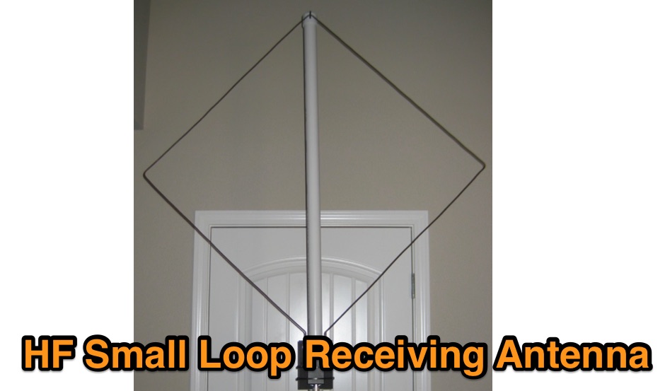
 Four or Five turn one meter loop antenna for 80 and 160 meter band. This home made receive only antena can be assembled in a small place.
 -
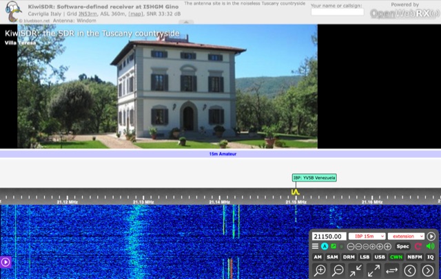 A software defined receiver located in Tuscany Italy with a Windom antenna convering HF bands
 -
 Mitigating impulse-type noise, a common challenge in the **HF radio spectrum**, often requires specialized processing before the signal reaches the transceiver's receiver stages. The NR-1 addresses this by functioning as an RF interference removal device, specifically a noise blanker, targeting transient noise sources. Its operational range extends from 1.6 MHz to beyond 70 MHz, making it suitable for various amateur radio bands and general shortwave listening applications. Unlike QRM eliminators or X-phasers, the NR-1 does not require a separate noise antenna for its operation, simplifying its integration into existing station setups. The device's design focuses on wideband performance, allowing its use both within and outside the allocated amateur radio frequencies. Documentation detailing its operation is available, providing insights into its technical specifications and deployment. This unit is a hardware product, conceptualized and implemented by SV3ORA.
 -
 This page describes a couple of parts box medicine bottle antennas that you can build. The ground side of the capacitor is soldered to the ground of the BNC connector. The positive side of the capacitor takes 5 turns around the toroid and is soldered back to itself. The center pin of the BNC connector takes 5 turns around the toroid and then continues on to the wire wound inductor. From there the antenna continues with an attached piece of wire.
 -
 Explains the fundamental purpose of a repeater, detailing how these automated relay stations overcome distance and terrain limitations for VHF/UHF communications. It traces the historical development from early Bell Telephone Labs "relay" stations in 1922 to Art Gentry, W6MEP's, pioneering K6MYK amateur radio repeater in the mid-1950s, which remains active today. The resource clarifies the distinction between simplex and duplex operation, including the unique function of a "parrot repeater" for single-frequency recording and playback. Delving into the internal workings, the guide breaks down a repeater into its core components: the antenna system, feedline (often _Heliax_ or hardline for minimal loss), duplexer, receiver, transmitter, and controller. It emphasizes the critical role of the duplexer in preventing receiver desensitization by isolating transmit and receive signals, even with distinct frequencies. The discussion highlights the importance of high-performance, durable antennas and low-loss feedlines, citing examples of equipment installed in the 1960s and 1970s that are still in perfect working order. Operating a repeater is also covered, with an explanation of frequency offset (e.g., the 600 kHz standard for 2 meters) and the function of _CTCSS_ (PL tone) for access. It outlines standard input/output offsets for various bands, from 6 meters to 23 centimeters, while noting regional variations. The guide also touches on features like autopatch and Digital Voice Recorders (DVRs), providing a solid foundation for understanding repeater technology and usage.
 -
 Listen to HF communications via the KiwiSDR online receiver located in Badgad IRAQ locator LM23fh. This web receiver is running a MLA 30+ antenna and can be tuned easily on all HF bands from 10 to 80 meters.
 -
 This study details a reception comparison between vertical and horizontal active loop antennas, specifically two identical _Wellgood active loop antennas_, on various HF bands. The experiment, conducted in a densely populated QRM-prone area, monitored FT8 signals over a 24-hour period using two identical receivers. The methodology involved direct comparison of signal reception across the HF spectrum, aiming to identify performance differences based on antenna orientation. The results indicate that vertical loops demonstrated superior performance on higher bands (10m, 15m, 20m), while horizontal loops excelled on lower bands (30m, 40m, 160m), particularly for receiving long-distance (DX) signals. The horizontal loop's advantage on lower bands is attributed to potentially better low-angle performance and reduced sensitivity to man-made noise, yielding a **2-3 S-unit** improvement on 160m. The study provides practical insights for optimizing antenna placement in challenging urban environments, noting that the horizontal loop consistently showed a **10-15 dB** signal-to-noise ratio improvement on lower bands.
 -
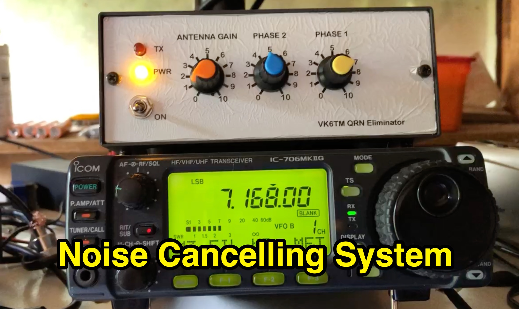 Learn how to improve reception on the hf bands by setting up a noise cancelling system that nulls out local interference. This article describes a system using a 'Main Station Antenna' to receive a wanted signal and associated QRM, and an 'Auxiliary Antenna' to pick up unwanted interference. Gain and phasing controls are used to reduce/remove interference, leaving only the wanted signal. Tips are provided based on the author's personal experience, applicable to commercial noise cancelling products, kit form, or homebrew setups. Discover the importance of configuring the 'Auxiliary Antenna' to optimize your system and improve readability of wanted stations.
 -
 The most basic form of repeater receives communication on one frequency and re-transmits it on a different frequency, a process known as duplex communication. This capability significantly extends the range of handheld and mobile radios, as repeaters are typically situated at elevated locations with high-gain antennas and greater transmit power. Repeaters commonly operate with FM modulation on the VHF (30 MHz – 300 MHz) and UHF (300 MHz – 3 GHz) amateur bands, which are ideal for portable and mobile devices. Access to repeaters is often controlled by a CTCSS or PL tone, an inaudible signal that prevents the repeater from retransmitting background noise. This mechanism ensures efficient use of the frequency and prevents illegal continuous transmission. Canadian regulations, for instance, require an Advanced amateur radio license and an available frequency within the band to set up a repeater, each assigned a unique call sign and transmit frequency. Configuring a radio for repeater use involves knowing the repeater's transmit frequency, its receive frequency offset (e.g., -600 KHz for VHF or +5 MHz for UHF), and the necessary CTCSS tone. The article references resources like Repeater Book for locating repeaters and provides practical examples for initiating and concluding a basic repeater session, emphasizing clear identification and concise communication.
 -
 This is a 50 MHz WebSDR receiver, located in Ashford, CT, USA FN31VU using a deltaloop turnstile horizontally polarized omnidirectional antenna.
 -
 This project details the development of a modular direct conversion (DC) receiver designed for experimental flexibility in amateur radio and HF signal listening. The mainframe integrates a diplexer, DBM, and AF amplifier, supporting interchangeable local oscillator and antenna filtering setups. A tunable passive HF preselector complements QRP Labs bandpass filters for enhanced signal reception. Utilizing a NanoVNA for precise tuning, the receiver achieves improved signal-to-noise ratios across amateur and non-amateur bands, making it a versatile platform for further RF experimentation.
 -
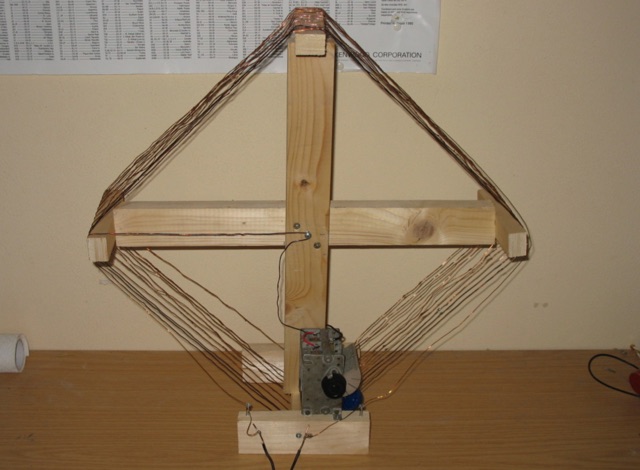 This loop antenna is intended to be connected as an antenna for receivers that do not have a built-in antenna such as an HF set or an old tube radio. This square barrel is wound on a wooden frame. It consists of two windings that are galvanically isolated from each other, a main and a coupling winding. The diameter is about 40 cm.
 -
 Effective suppression of harmonics and parasitic radiation from HF transmitters is crucial, especially with the increasing sensitivity of VHF/UHF radio channels to interference. This project details a hybrid low-pass filter (LPF) designed to operate across the HF bands up to 51 MHz, making it suitable for 6-meter band operations while providing deep VHF/UHF suppression. The design addresses the challenge of modern interference landscapes, where even microvolt-level signals can disrupt wireless sensors and other simple VHF/UHF receivers. The filter utilizes a single elliptic link, combining high cutoff steepness with robust suppression in the hundreds of megahertz range. A key feature is the use of only two standard capacitor values, simplifying construction and component sourcing. The article provides a detailed schematic, performance characteristics, and _RFSim99_ model file, demonstrating a reflection coefficient S11 below 0.017 (VSWR < 1.03) across 1-51 MHz, ensuring minimal degradation to the antenna system. Construction notes include coil winding specifications and capacitor selection guidance, with recommendations for _FR-4_ assembly. Two capacitor sets are presented, with the first variant recommended for its lower RF current demands, keeping currents below 3 A at 1 kW passing power at 51 MHz. Fine-tuning involves adjusting frameless coils, with considerations for capacitor tolerance and high-frequency capacitance measurement accuracy.
 -
 The Aziloop DF-72 antenna system provides 72 K9AY headings and 36 loop axes, allowing for rapid switching in 60 ms. It integrates a switchable 18 dB preamp, a 4-step attenuator (0-18 dB), and four 7-pole preselection filters to optimize receiver performance. The K9AY load is adjustable from 250 Ohm to 950 Ohm in 50 Ohm increments, offering flexibility for various receiving conditions. Control is managed via an intuitive Windows UI, supporting Local, Client, or Server modes, with headless remote operation possible through the built-in Ethernet Server. _Omni-Rig_ support facilitates auto-filter selection, PTT muting, and Rig-Sync functionality, enhancing integration with existing station setups. Designed by _GW4GTE_, the system utilizes a low visual impact, small-footprint antenna with orthogonal loops and an earth connection. It is suitable for general monitoring, co-channel station resolution, basic direction finding, and interference reduction across the VLF to HF spectrum.
 -
 Operating amateur radio satellites presents unique challenges, particularly concerning antenna design and signal propagation. Juan Antonio Fernández Montaña, EA4CYQ, recounts his three-year journey into satellite communication, starting with initial guidance from EB4DKA. His early experiments involved a portable 1/4 wave VHF antenna with four 1/4 wave ground planes, designed for hand-held use to adjust polarity. This setup, paired with an FT-3000M transceiver, allowed full-duplex operation on **VHF** transmit and **UHF** receive, proving effective for early contacts on satellites like AO27, UO14, and SO35. EA4CYQ's experience highlights the critical role of coaxial cable loss and antenna polarization. After encountering significant signal degradation with longer RG213 runs, he experimented with a 1/2 inch commercial cable, noting improved reception but persistent fading due to varying satellite polarities. This led to the construction of an **Eggbeater II** antenna, an omnidirectional UHF design offering horizontal polarization at the horizon and circular right polarization at higher elevation angles. Subsequent modifications resulted in the directional **TPM2** antenna, which provided sufficient gain for LEO satellites with a wide 30-degree lobe, enabling consistent contacts from his home station. The article concludes with practical insights on the performance of the Eggbeater II for both UHF and VHF, and the TPM2 for UHF, emphasizing their utility for portable and fixed operations. EA4CYQ's journey underscores the iterative process of antenna development and the importance of adapting designs to overcome real-world propagation challenges in satellite communications.
 -
 Early 20th-century transatlantic wireless communication efforts involved distinct technical approaches by Reginald Fessenden and Guglielmo Marconi. Marconi's systems, operational until approximately 1912, primarily utilized _spark technology_ for wireless telegraphy, facilitating Morse code communication between ships and across oceans. His Poldhu station in December 1901 radiated signals in the MF band around 850 kHz, later evolving to 272 kHz in October 1902, and eventually 45 kHz by late 1907 with increasingly larger antenna structures like the pyramidal monopole and capacitive top-loaded arrays. Fessenden, conversely, focused on _continuous wave transmission_ for wireless telephony, recognizing its necessity for speech. His transatlantic experiments in 1906 employed synchronous rotary-spark-gap transmitters and 420-foot umbrella top-loaded antennas at Brant Rock, MA, and Machrihanish, Scotland, tuned to approximately 80 kHz. Fessenden later utilized the _Alexanderson HF alternator_ at 75 kHz by late 1906 for pure CW transmission, integrating a carbon microphone for amplitude modulation. Receiver technology also differed, with Marconi initially relying on untuned coherer-type detectors, later developing the magnetic detector in 1902, while Fessenden's CW approach necessitated more advanced detection methods.
 -
 Demonstrates the construction of an active loop converter specifically designed for the Low Frequency (LF) bands, addressing common localized noise interference in LF reception. The design integrates a sharply tuned circuit and a tuned loop antenna, utilizing the loop as the sole tuned inductive element. By applying positive feedback, the converter significantly increases the loop's effective Q, achieving factors between 1000 and 2000, which sharpens tuning and reduces noise. The circuit employs an _NE602_ mixer stage, feeding its output to an HF receiver, with a crystal-locked local oscillator at 4 MHz. A 20-turn, 0.8-meter square loop antenna with 500 uH inductance is detailed, connected via 2 meters of figure 8 flex cable. The converter offers three selectable frequency bands: 195-490 kHz, 150-220 kHz (including the New Zealand amateur band), and 128-160 kHz (covering the European amateur band). Performance measurements indicate an effective 3dB bandwidth of approximately 100 to 200 hertz at 200 kHz. The article provides insights into component selection, including an _LF353_ op-amp and a trifilar wound transformer on a ferrite core. Sensitivity figures are presented, showing 7.5 uV of converted output per 1 uV/meter signal strength into a 50-ohm load, or 37.5 uV into an _FRG7_ receiver, highlighting its capability to extract weak signals from noise.